CC-2 Test Items : Pavement Construction / Cross Section
Pavement Demolition
This reconstruction project required the removal of CC-1 pavement structures. CC-1 had included a conventional flexible pavement on medium strength subgrade (MFC) and a flexible pavement with asphalt stabilized base (MFS). It also included a rigid pavement with an Econocrete stabilized subbase (MRS), (Figure 1). For this construction effort, only part of the MRS was demolished. The existing PCC slabs were removed and most of the exposed Econocrete subbase was retained.
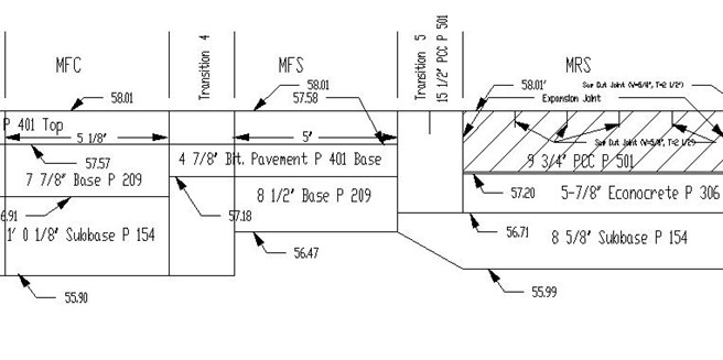
Figure 1. Elevation of CC-1 Test Pavement
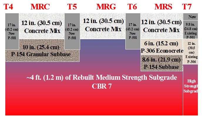
Figure 2. Elevation of CC-2 Test Pavement
The CC-2 project replaced the test items of CC-1 with three new pavement test items. The new items consisted of PCC on conventional base (MRC), on grade (MRG), and on the existing Econocrete stabilized subbase (MRS), (Figure 2). Three transitions were also rebuilt, two of which were relocated. A fourth transition was treated with a thin concrete overlay. The work covered a width of 66 ft. and a length of 325 ft. The breakdown was as follows: transition 4, station 300 to 325; MRC, station 325 to 400; transition 5, station 400 to 425; MRG, station 425 to 500; transition 6, station 500 to 525; MRS, station 525 to 600; and transition 7, station 600 to 625. The work schedule provided the guide for the reconstruction effort (Figure 3, A, B and C).
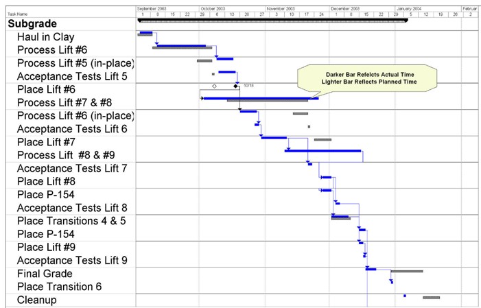
Figure 3. Construction Schedule – Part (A)
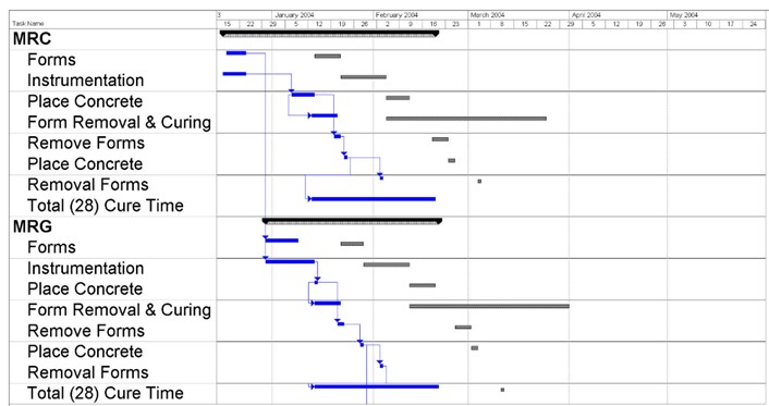
Figure 3. Construction Schedule – Part (b)

Figure 3. Construction Schedule – Part (c)
The asphaltic concrete pavement layer and base, station 300 to 475, were removed between April 3 to April 11, 2002 as part of construction cycle three (CC-3) over the low strength subgrade. The effort took 4 work days. Demolition continued on October 22, 2002 when a 16-inch rotary saw cut was made through the existing PCC slabs and the Econocrete subbase at station 525. The J.B.T. Building Co.’s excavator equipped with a hydraulic hammer, demolished all rigid pavement material between stations 475 and 525. The material consisted of the PCC transition, PCC slabs, and part of the Econocrete subbase. Two dump trucks were used to cart the material off-site. The excavator was refitted with a small bucket and thumb for loading the trucks.
Excavation and Removal
The crushed stone base and subbase material, P-209, and the granular subbase material, P-154, were excavated and removed from the NAPTF site, station 305 to 475. J.B.T. Building Co. used an excavator, equipped with a large bucket, to load a dump truck. The excavation reached a clean medium strength subgrade surface, the material designated as DuPont Clay. The clean surface extended to the sides and bottom of four trenches which were previously excavated for CC-1 post-traffic investigations. The trenches had been positioned transversely in the test items and were of 4 ft. long, 2 ft. deep, and 60 ft. wide.
This effort took 9 work days.
Excavation and Retention
About 3 1/2 to 4 ft. of clean subgrade material, DuPont Clay, were excavated and stockpiled east of the work area. The excavation reached elevation 53 and extended from station 305 to 500 at the full width of 66 ft. Stockpiles were established east of the work area at station 540 to 925, south side, and station 740 to 930, north side. The J.B.T. Building Co. used an excavator, front end loader, and a dump truck.
The area between stations 500 to 525 was ramped from elevation 53 to 58 to provide access for construction vehicles. The ramped area covered the full width of 66 ft. Clean subgrade material was used, with the source being the remainder of a supply stockpiled on the south side (section 3.2). The clean subgrade material replaced a contaminated mix of crushed stone, P-209, granular material, P-154, and subgrade material, P-152, all of which were previously used for the ramp.
The entire subgrade surface, station 305 to 525, was covered with plastic sheets when work was not in progress. This prevented moisture loss from the subgrade. Covering the subgrade surface remained a standard procedure throughout the construction.
This effort took 7 work days.
Pavement Reconstruction
Specifications
The material specifications applicable to the various layers of the pavement structure were:
- Item M-102 M Pavement Removal
- Item P-152 LM Subgrade (Medium Strength)
- Item P-154 M Subbase Course
- Item P-501 M1 Portland Cement Concrete Pavement
The CBR (California Bearing Ratio) measurements provided the basic criterion for the various lifts of the reprocessed subgrade. A CBR reading is the average of three measurements taken from three penetrations made by the instrument into the compacted subgrade surface. The average is considered valid if the individual readings lie within a range of 1.5. The overall target CBR value for the medium strength subgrade was 7. For the purpose of uniformity, every subgrade lift was divided into two lots, north and south, each extending for two test items (station 325 to 400 for MRC and station 425 to 500 for MRG). Each lot was divided east and west, forming four sublots with two under each test item (Figure 4). CBR measurements were taken near the center of each sublot at a distance of 9 to 14 ft. from the longitudinal centerline of the test area. This location placed the measurements in what would eventually be the wheel path of the test vehicle. Companion moisture samples were also taken from the subgrade for processing in the moisture analyzers.
The following procedure was used for the acceptance of each lift of the reprocessed subgrade:
- The difference in the CBR ratio between two adjacent sublots, east and west, was not to exceed 2.0.
- The difference in the CBR ratio between two side by side sublots, north and south, was not to exceed 1.0.
- The difference between the average CBR for each lot was not to exceed 2.0.
- Targeting a CBR of 7, the average CBR of both lots (the entire lift) was to fall between 5.5 and 8.0.
Requirements of the first and third bullet above did not apply to subgrade lifts 8 and 9 which were under MRG only.

Figure 4. CBR Sublots
Drying The Subgrade Material
On September 11 and 12, 2002, 1,000 cubic yards of subgrade material (DuPont Clay) were taken from the storage yard and placed in the NAPTF building on the south side, east of the construction area, station 540 to 800. The J.B.T. Building Co. used an excavator, a front end loader, and two dump trucks to move these materials. The front end loader and excavator were used to take material from the newly placed supply stockpile and form a processing strip on the north side of the facility for drying the clay. The strip, consisting of loose subgrade material, was 30 ft. wide by about 3 ft. high and 155 ft. long, extending from station 760 to 915.
Random samplings of the subgrade material, taken from the supply stockpile, revealed the moisture content to be about 42%. Each sample consisted of about 600 grams of clay with individual pieces selected from throughout the stockpile. The test for moisture content involved drying the 40 gram clay samples in a microwave oven in accordance with the procedure outlined by the American Society for Testing and Materials (ASTM) D 4643. Moisture analyzers were also used throughout construction. Data acquired during the original pavement construction at the facility (CC-1), indicated moisture content between 30 and 31% would yield a CBR of about 7 in the compacted medium strength subgrade. A CBR of 7 was selected as the desired value for the subgrade in the CC-2 construction.
The upper 12 to 16 inches of the processing strip, the depths of clay which could be reached by the blades of the tiller, were designated as a lift. Four lifts were individually placed on the strip and processed. The tiller pulverized each lift with periods of time left in between operations for air drying. The procedure was continued until the moisture content of the subgrade material approached 31%. Four 3 1/2 ft. electric fans were placed around the processing strip to expedite the drying. The fans ran day and night including weekends. After drying, the lifts were removed and stockpiled for ultimate placement in the reconstructed subgrade. Each lift was estimated to yield 100 cubic yards of compacted material. The processed stockpile, which was loosely placed, occupied the area from station 540 to 735, north side. The stockpile was kept covered with plastic sheets unless material was either added or taken for placement. J.B.T. Building Co. used an excavator, front end loader, and bulldozer to remove the various lifts of the processing strip, place them in the ready (processed) stockpile, and then place a new lift on the strip.
The work described above was completed on December 3, 2002, after which the construction of the actual subgrade lifts of the test pavement began. However, work was discontinued after January 15, 2003 due to cold weather. Freezing conditions began to affect the surface of the subgrade, and CBR tests could not be conducted. The first 5 subgrade lifts had been placed, compacted, and FAA approved. Work resumed on September 2, 2003, with the drying effort on the clay material which continued until December 15, 2003. The aforementioned activities of hauling new subgrade material into the NAPTF building, placing the material in a processing strip, and tilling various lifts prior to placement were repeated. Differences are noted in the paragraphs that follow.
On September 2 to 5, 2003, 1,500 cubic yards of subgrade material (DuPont Clay) were taken from the storage yard and placed in the NAPTF building on the south side, east of the construction area, station 590 to 990 (Figure 5). The processing strip was re-established on the north side, but to a greater length, 270 ft. (station 660 to 930). The width was again 30 ft. Although more than 200 cubic yards of subgrade could be processed at one time (Figure 6), the lifts were removed at shallower depths for the purpose of uniformity. Six lifts were removed in all, each in excess of 100 cubic yards (compacted yield). The lifts were placed in the processed stockpile, station 540 to 630, north side. The material was stockpiled at a moisture content of about 34%. Experience had shown that some excess moisture (above the targeted 30% to 31%) should be allowed to account for additional loss during subgrade reconstruction. Losses occurred from placing, tilling, and rolling.
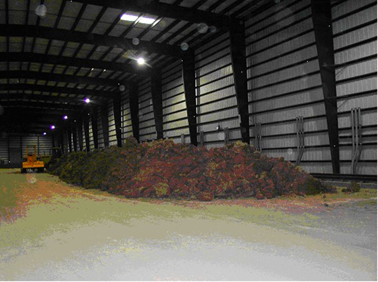
Figure 5. Subgrade Stockpile
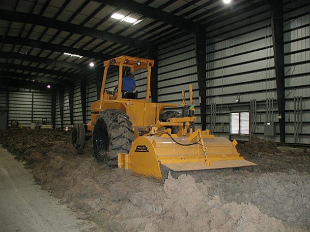
Figure 6. Tilling Subgrade Material on Drying Strip
Four 3 1/2 ft. electric fans were used around the processing strip (Figure 7). The fans ran 24 hours a day including weekends. Additionally, two overhead fans located at the roof of the facility also ran for 24 hours a day including weekends. Their associated louvers, one on the north wall and one on the south wall, were left in the open position enhancing the air flow.
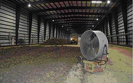
Figure 7. Fans Around Drying Strip
Large twin fans (5 ft. in diameter) were placed in the east overhead doorway and ran during the work day. The overhead door was lowered to the frame of the twin fans. The west overhead door and the side doors, in the vicinity of the processing strip, were left open during the day.
Watering System Modifications
A steel bridge deck finisher (BDF) vehicle was used to move a watering system for increasing the moisture content of the subgrade, subbase, and base layers during the CC-3 pavement reconstruction on the low strength subgrade, April 8 to August 17, 2002. The BDF consisted of two end units with rollers which could ride the rails used by the test vehicle. Each side of a center span was bolted to one of the end units. The entire assembly spanned 71 ft. and was set in place on the inner rails.
The BDF was fitted with a 2 inch PVC pipe over the entire span. Brass nozzles, spaced at 4 ft., were fastened to the underside of the pipe. The north side of the pipe was fitted with steel plumbing for attachment to a hose providing water from the NAPTF supply. The overall operational effect of the watering system resembled rainfall. Two steel struts were used to bolt the unit to the east end of the NAPTF test vehicle. The vehicle provided the motive power. Watering passes were run at 0.50 ft./sec. A self-propelled capability was installed on the BDF. The BDF was outfitted with two roller mounted steel platforms for supporting CBR measuring units.
For the current effort, CC-2 medium strength subgrade, the BDF was stiffened with an overhead trussed structure. The BDF was used to water various subgrade lifts of the pavement structure in order to increase moisture content and to water the surface of the completed concrete pavement to limit upward curling at the corners of the individual slabs. It was also used as the mounting platform and reaction support for conducting the CBR tests on the completed subgrade lifts Figure 8 shows the BDF being propelled by the test vehicle while watering one of the tilled subgrade lifts.
This effort took 6 work days.
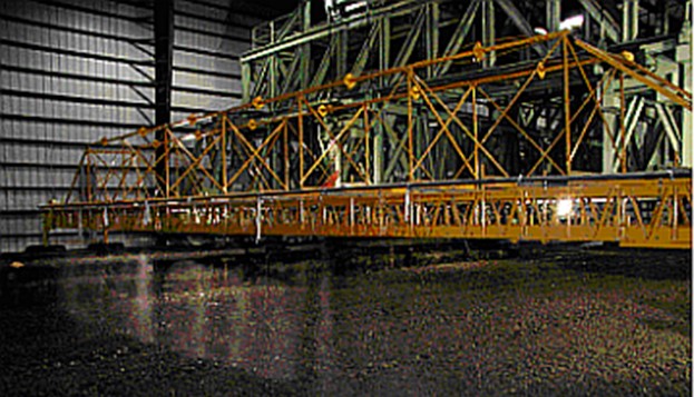
Figure 8. Watering Subgrade Lift
The subgrade surface after the excavation was reworked was designated as lift 0. The remaining 4 ft. of subgrade consisted of replacing and reworking the stockpiled material in 6 in. lifts designated as lift 1 to lift 9. The lifts were about 8 in. in depth when placed, but became 6 in. when compacted. The material source was the excavated stockpiles, the processed stockpile, or the upper lift of the processing strip. The overall procedure was as follows:
- The surface of lift 0 was tilled.
- Random samples were taken and moisture tests run. Data acquired from the initial CC-1 construction at the NAPTF indicated that moisture content between 30% and 31% would achieve the target CBR of 7 for the compacted medium strength subgrade.
- The surface was watered and retilled when the moisture content was found to be low. The number of watering passes was estimated from the moisture gain required.
- The procedure of the above step was repeated until the moisture content was achieved.
- When the moisture content was found to be high, the surface was simply tilled and air dried until the desired moisture content was reached (Figure 9).
- The surface of the lift was then compacted with a roller (Figure 10). Following compaction, the lift was covered with plastic sheets which were removed only to perform other work.
- CBR and moisture readings were taken north and south of the pavement centerline in accordance with the specifications outlined in section 3.1. The CBR electric motor unit was attached to one of the roller mounted steel platforms on the BDF. The BDF in turn was attached to the test vehicle which moved it into position. Figure 11 shows a CBR penetration in process.
- Lift 0 was accepted by the FAA Construction Manager based on the CBR values complying with the specifications of section 3.1.
- The plastic sheets were removed.
- Lift 1 was then placed, and the above steps were repeated for lift 1 and the remaining Lifts, 2 to 9. Table 1 shows the test data for an approved lift 6.
This effort took 74 days.
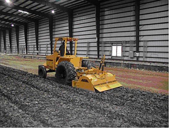
Figure 9. Tilling Subgrade Lift
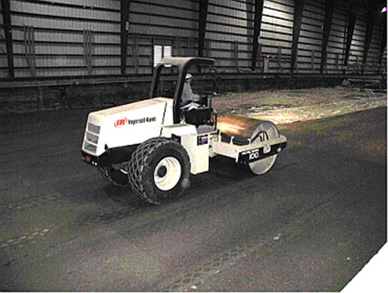
Figure 10. Steel Drum Vibratory Roller on Subgrade Lift
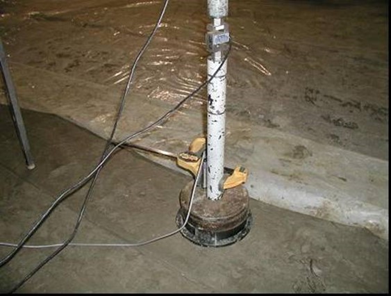
Figure 11. CBR Measurement
Table 1. CBR Data, Subgrade, Lift 6

The placement procedure for each successive lift involved removing the clay from one of the material sources and placing it at the east end of the subgrade reconstruction area. A front end loader was used, and at times a dump truck was used, to deposit the material at the east end location. A bulldozer was used to push the material in place (Figure 12), after which the procedure described in the above steps was carried out. J.B.T. Building Co. provided the effort.
Two roof fans ran during the construction, and the associated louvers, one on the north wall and one on the south wall, were left open. The condition was maintained during evenings and weekends when a significant amount of drying was needed. Side doors were left open during the work day, as well as the large overhead doors at the east and west ends of the building.
Two moisture analyzers were used to determine the moisture content of the various lifts, although the microwave oven was sometimes used to determine when the moisture content of a lift was coming within range.
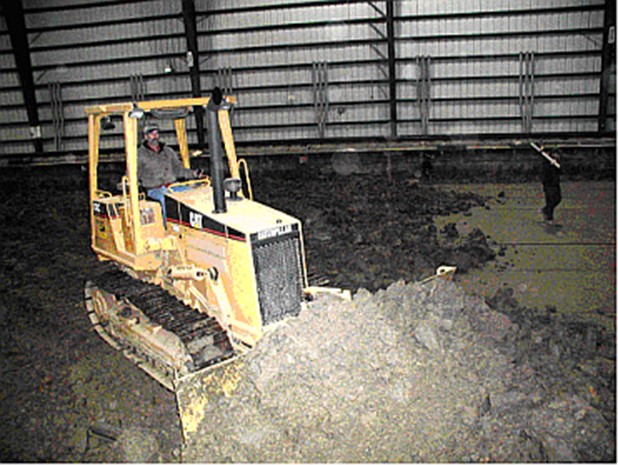
Figure 12. Bulldozer Moving Subgrade Lift Into Place
Lifts 0 to 5 were compacted with a dual steel drum vibratory roller (Figure 10). Lifts 6 to 9 were compacted with 22,000 lb. water ballasted rubber tire roller (Figure 13). The rubber tire roller had seven wheels and was believed to provide better compaction by virtue of imparting a kneading action to the subgrade material. After compaction, lifts 7, 8, and 9 were pretested with a hand held Torvane device. The Torvane yielded an index value representative of the torsional shear strength of the compacted subgrade. The value correlated with the CBR value and gave an indication of whether the CBR for the lift could be expected to fall within the specified range. The instrument proved to be a time saver by virtue of requiring just minutes to operate, and only a trial path of the subgrade lift had to be rolled. The remainder of the lift was compacted when the Torvane readings were found to be in the appropriate range.
Lifts 8 and 9 were partial lifts in that they were slightly thinner and much shorter. Each had a compacted thickness of 5 inches rather than 6 inches. Lift 8 was located under MRG and transition 6 (100 ft. in length). Lift 9 was located under MRG (75 ft. in length). Lifts 0 to 7 were located under transition 4, MRC, transition 5, MRG, and transition 6 (225 ft in length). Lift 9 was placed after the concrete for transition 5 was placed.
The top surfaces of the uppermost lifts under MRC and MRG, lifts 7 and 9 respectively (Figure 2), were surveyed establishing a 5 ft. grid for the measurements. The FAA Construction Manager conducted the survey. Adjustments were made to the surfaces with the excavator using a gentle drawing action. This technique allowed the large bucket, with its “knife” edge, to produce thin shavings and lower the high areas in a controlled manner (Figure 14). The surfaces were again rolled, surveyed, and found to comply with the design specifications. The subgrade was accepted by the FAA Construction Manager.
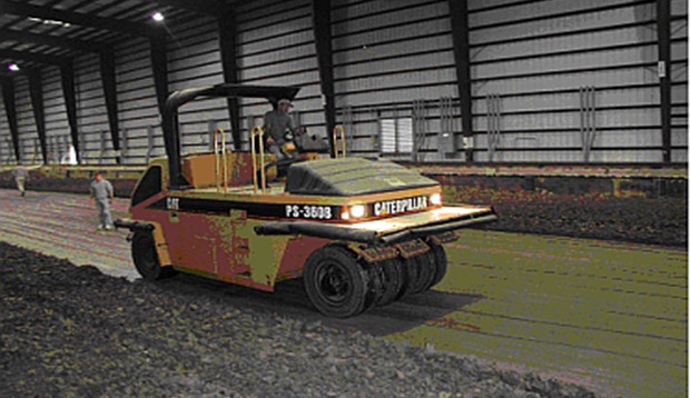
Figure 13. Rubber Tire Roller on Subgrade Lift
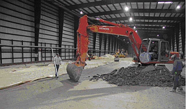
Figure 14. Shaving Subgrade to Specified Grade
On November 25, 2003, Glasgow, Inc. deposited seven truckloads of granular base material, P-154, west of the construction area. The piles were watered with soaker hoses, controlled by a timer, in order to enhance compaction after the material was placed. The excavator was used to remove excess clay and lower the subgrade to the level of the top surface of lift 7, in the area of station 305 to 325, in preparation for base material placement. This effort took 11 work days.
The front end loader was used to deposit the stockpiled granular material, P-154, over lift 7 of the subgrade. The bulldozer was used to distribute it from station 305 to station 410, where it mated up with lift 8 of the subgrade (Figure 15). The granular material was rolled with a small steel drum roller to a compacted thickness of 5 in., forming lift 1 of the base for MRC. A hand tamper was used to compact the edges.
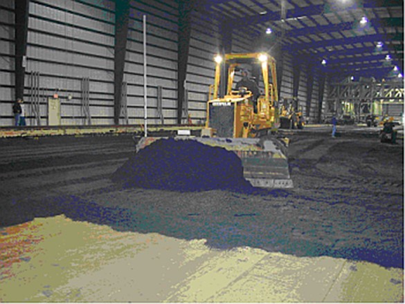
Figure 15. Bulldozer Spreading First Lift of Granular Base
A rotary saw was used to place a transverse cut through the existing asphalt pavement at station 300. The excavator was used to lift out the excess material above subgrade lift 7 between stations 300 and 305. The excess material consisted of asphalt, P-401, and crushed stone base, P-209, exposing granular subbase material, P-154 (CC-3, low strength subgrade). A backhoe was used to excavate subgrade material down to the level of the top surface of lift 7 between stations 410 to 425. The exposed area of subgrade was rolled with a small steel drum roller. It then received a layer of P-154 which in turn was rolled. Lift 1 of the granular base material was now completed from station 300 to 425. Special attention was given to grading, rolling, and tamping the areas between station 300 to 325 and 400 to 425. These areas formed the base for the placement of transitions 4 and 5, respectively. Lift 1 of the base material remained covered with plastic sheets when no work was in progress.
Placement of Transitions
Lift 2 of the base material was set in place following the placement and curing of transitions 4 and 5. It was set between the transitions at a compacted thickness of 5 in. Glasgow delivered an additional seven truckloads of material which made up the supply. Lift 2 was placed with a backhoe, bulldozer, small steel drum roller, hand operated tamper, and small tractor grader. The total compacted thickness of base material under MRC was 10 in. J.B.T. Building Co. provided the construction effort. Upon completion, the base surface was surveyed by the FAA Construction Manager using a 5 ft. grid. Adjustments were made with the tractor grader (Figure 16) guided by a laser level. The surface was again rolled, and a final survey taken. The surface was found to comply with design specifications. The granular base was accepted by the FAA Construction Manager.
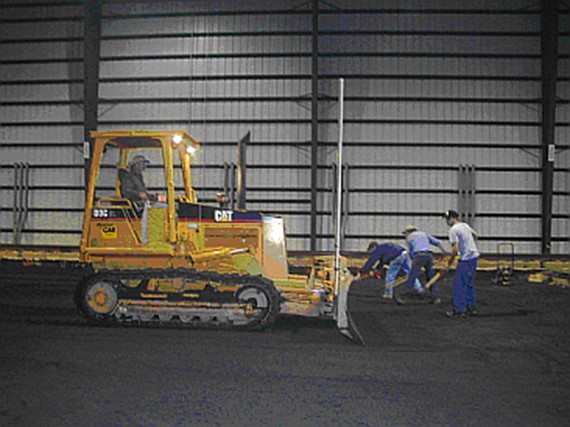
Figure 16. Tractor Grading Granular Base
Plywood forms were first placed for transitions 4 and 5. The forms for each transition formed a box with interior dimensions of 25 ft. (length), 60 ft. (width), and 17 in. (thickness). The two boxes rested on lift 1 of the compacted granular base, P-154, and occupied stations 300 to 325 and 400 to 425. The top of the forms were set to grade with a laser level. The west edge of transition 4, station 300, was actually formed by the pavement material which remained from CC-3, low strength subgrade, namely 5 in. of asphalt pavement over 10 in. of crushed stone base. A 2 1/4 in. wood strip was nailed onto the top of the asphalt to complete the west side of the forms. Three rows of steel dowels were placed on wire baskets and set in place 8 1/2 in. above the surface of the granular base within each set of forms (Figure 17). The rows were centered below what would eventually be three saw cuts at the surface of the concrete which were intended to isolate shrinkage cracks. One cut would be a transverse cut 12 ft. 6 in. from either the east or west edge of the transition. The other two would be longitudinal cuts, one located 20 ft. 6 in. from the north edge of the transition, and the other 20 ft. 6 in. from the south edge of the transition. The steel dowels were set perpendicular to what would be the saw cut lines. The dowels were 20 in. long and had a diameter of 1 1/4 in.
The effort took 17 work days.
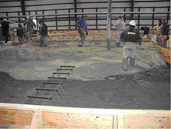
Figure 17. Dowels at Transverse Joint Location in Transition 5
Plastic sleeves were set in place on the forms to eventually receive 1 in. steel “speed” dowels connecting the transitions to the concrete slabs of the test items. The sleeves were positioned on the inner face of the transverse sections of the forms, 6 in. down from the top edge and spaced 12 in., forming a line 58 ft. long. They were placed on the east side of transition 4 and the east and west sides of transition 5. They were to remain embedded in the concrete after the forms were removed.
The concrete for transitions 4 and 5 was placed on December 9, 2003. The compressive strength was specified as 4,500 psi. The concrete was placed using a 52-meter pump (Figure 18). Slump and percent air content tests were taken before and after pumping. The pump rested on the asphalt pavement (CC-3, low strength subgrade), west of station 300. The concrete was leveled with a 25 ft. power screeder which rode on the top of the transverse forms. The screeder was powered by a compressor which sat outside of the NAPTF building. The screeder was guided with tensioned steel cables and moved along its path by the use of a hand operated crank. The concrete surface was finished with a bull float and trowel. The transitions were covered with thermal blankets a few hours following placement.
The following day, the blankets were removed and saw cuts were placed in the top surface of the concrete. Preliminary cuts were first made with a small “soff-cut” saw. Final cuts, measuring 1/4 in. in width and 3 in. in depth, were made with a full size rotary saw. The surface of the concrete was swept clean following the sawing operation. The surface was then wet with a powered sprinkler, covered with burlap, again sprinkled, and finally covered with the thermal blankets. The forms were removed 3 days after placement. The wet curing was discontinued 13 days following placement. All coverings were removed, and the surface swept clean. A sprinkler was used to spray the concrete surface with two coats of a curing compound.
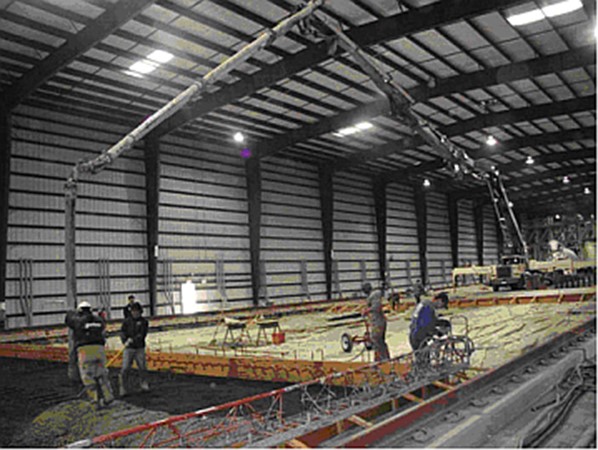
Figure 18. Placing Transition 5
Transition 6 was placed on December 30, 2003. The procedures were similar to those for transitions 4 and 5. There were several differences however. First, some excavation of subgrade was required in the area of concrete placement, station 500 to 525. It involved a combination of lift 9 and the material ramped for construction access. J.B.T. Building Co. used an excavator with the large bucket. Also, some narrow inserts of laminated wood and plastic foam were set transversely in the open area, contained by the forms, at the level of what would be the concrete surface. The inserts, when removed, provided depressions in the concrete, north and south, which accommodated the placement of taxiway lights. The lights were placed for experimental purposes. They were subjected to landing gear loading when the traffic tests were conducted.
A 36-meter concrete pump was used for placement, rather than a 52-meter pump, since the reach from the staging area was shorter than it was for transitions 4 and 5. The original concrete slabs (CC-1, medium strength subgrade) were temporarily left in place to provide a closer working platform, station 525 to 600. Transition 6 was located at station 500 to 525. The forms and inserts were removed the day following placement. Removal of the east transverse form had to await demolition of the CC-1 concrete slabs, station 525 to 600 (section 3.8). Wet curing of transition 5 was discontinued 8 days after placement. Curing compound was applied that same day. United Concrete provided the construction effort for transitions 4, 5, and 6. The transitions were accepted by the FAA Construction Manager.
Placement of MRC and MRG
The test items were designed with overall dimensions of 75 ft in length and 60 ft in width. They each contained twenty individual slabs forming four longitudinal lanes with five slabs in each lane. The slabs were 15 ft by 15 ft by 12 in. in thickness (Figure 19). The concrete specifications (Table 2) called for 50% class C flyash to be in the cementious mix. The flyash was introduced to lower the flexural strength of the concrete and permit the use of a greater slab thickness. A greater slab thickness would help to mitigate upward curling of the slab corners and avoid premature top-down cracking, under loading, due to the lack of sufficient support. A flexural strength of 750 psi was targeted allowing a possible slab thickness of as much as 12 inches. These parameters were selected to also produce the desired load repetitions to failure of about 10,000 for the test items. The slabs of the original CC-1, medium strength subgrade, were 9 3/4 in. thick.
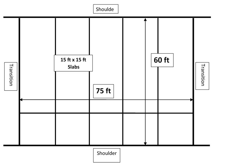
Figure 19. Plan View of a Single Test Item
Table 2. Concrete Mix Specifications for Test Items
|
Material
|
Proportions
|
|
|
|
# 57 Coarse Aggregate
|
1,685 lb/cubic yard
|
|
Sand ( C 33 )
|
1,555 lb/cubic yard
|
|
Cementitious Mix ( Type 1 Cement & Class C Flyash )
|
500 lb/cubic yard
|
|
Water
|
250 lb/cubic yard
|
|
Water – Cementitious Mix Ratio
|
0.50
|
|
Percent Flyash in Cementitious Mix
|
0.50 %
|
Both the mix and placement were in accordance with specification P-501 M1, Portland Cement Concrete Pavement, with the exception of the flyash content. This effort took 27 work days.
The CC-2 slabs were designed that the inner lanes would be doweled on all four sides. The slabs in the outer lanes were doweled on three sides, leaving only the free outer edges no doweled. The dowels were introduced in order to provide a uniform distribution of gear loading and to minimize damage in the event that premature top-down cracking occurred at the slab corners. Steel “speed” dowels, 1 in. in diameter and 18 in. in length, were selected for the construction. Each fit into a companion plastic sleeve which was embedded in a previous concrete placement. The slabs for each test item were placed on two different days, spaced about one week apart. One week was allowed prior to stripping the forms due to the slower set of the high flyash concrete mix, particularly in the cold weather.
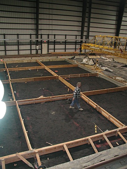
Figure 20. Layout of Forms in MRC
Plywood forms, 12 in. deep, were formed into boxes with interior dimensions of 15 ft. by 15 ft. The boxes were set onto the base material (granular base for MRC and subgrade for MRG) forming a “checkerboard” pattern, allowing ten of the twenty slabs to be placed on the first day (Figure 20). The top edges of the forms were set to the design elevation of 58.19 ft. using a laser level. The outer faces of the forms were braced against the base material in the open areas. Wood studs were used forming a webbed pattern, keeping penetrations of the base material to a minimum. The plastic sleeves for the dowels were fastened to the inner faces of the forms, 6 in. down from the top edge and spaced 12 in. cc. An exception was made for the end dowels which were spaced 13 in. from the slab corners in order to allow for proper end clearances with the dowels at right angles. This same adjustment had been made in setting the sleeves in the transitions. The transverse sides of the transitions served as forms for the east and west ends of the test items.
Steel dowels were set into place in previously embedded plastic sleeves in the east end of transition 4, east and west ends of transition 5, and west end of transition 6. The dowels were secured with epoxy adhesive. The exposed ends were covered with light grease. Instrumentation system sensors were set into place on both the forms and on the base material. The instrumentation system was designed such that the majority of the sensors would be set and embedded in the first concrete placement. Wires were run, connections made, and the first section of the instrumentation system completed and checked out. The wires were embedded in the base materials, just below the surface.
Due to the low temperatures anticipated in January and February, it was decided to first place only one slab and monitor the temperatures within the concrete. Slab 16 was selected at the southwest corner of MRC. It was placed on January 7, 2004. Conventional hand placement methods were used with the concrete being fed directly from the truck. The truck was positioned on transition 4. The concrete surface was treated with a broomed finish toward the end of the day. The slab was then covered with blankets. The blankets were removed two days later. Burlap strips were placed over the surface and then wetted down with a hose. The slab was again covered with blankets. The blankets were undisturbed for the remainder of the curing period except for brief occasions when additional water was added.
The outdoor air temperature was 21°F on the day and time of placement. The indoor air temperature within the NAPTF was 33°F. The temperature of the concrete was 65°F. Following placement, the temperature of the concrete dropped to 45°F at the top of the slab and 60°F at the bottom. The following day the temperature of the slab increased to a uniform 65°F. This was followed by a gradual decrease. It became apparent from the single slab placement that the temperature of the concrete could be held within a 40°F range, safely above the 32°F water freezing level.
The remaining nine slabs of the first set for MRC were placed on January 13, 2004 (Figure 21). A 36-meter pump was used to deliver the concrete to all the placement areas. The pump was positioned at transition 4. Slump and air content were measured on the concrete before and after the material passed through the pump. A slump of 3 in. and an air content of 4 1/2% were the target values. Placement progressed in the east-west direction, starting at the north side and completing on the south side. The concrete was set down in areas clear of the instrumentation system sensors. Sensors were hand packed with concrete prior to being covered (Figure 22). A hand held vibrator was used to help densify and distribute the concrete. When sufficient concrete was placed, each slab was set to grade using a 15 Ft. power screeder guided by tensioned steel cables (Figure 23). The screeder rode on the top edge of the forms and was powered by a compressor which operated outside of the NAPTF building. The screeder was moved along its path by the use of a hand operated crank. Finishing of the surface of the concrete was held to a minimum so as not to have an excess of water accumulate at the top. A bull float and trowel, positioned on long poles, were used. The surfaces were given a light broom finish at the end of the day. The direction of brooming was perpendicular to the path of the test vehicle. The slabs were then covered with thermal blankets.
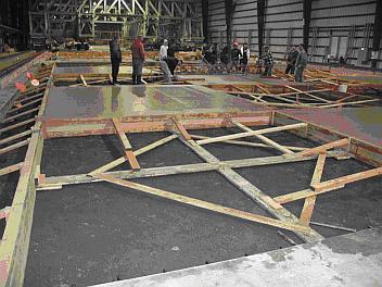
Figure 21. First Placement of Concrete in MRC
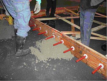
Figure 22. Hand Packing Concrete Over Sensors
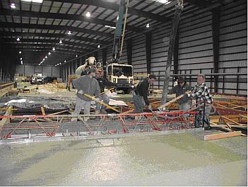
Figure 23. Power Screeder
The blankets were temporarily removed after two days. The slabs were covered with burlap strips and wetted down with a hose. The blankets were again placed, and the entire test item area was covered with plastic sheets. The setup remained undisturbed for the remainder of the ten slabs had to be placed in the test item.
The first ten slabs of MRG were placed on January 14, 2004. Procedures were the same for the slabs of MRC except for the positioning of the 36-meter pump. The pump was located at the staging area, station 500 to 600. Station 500 to 525 had previously been filled with transition 6.
The forms for MRC and MRG were removed about one week after placement. Forms bounding the north and south sides of the test items remained. The 1 in. diameter by 18 in. long steel dowels were then placed in the previously embedded plastic sleeves in the first set of ten slabs. Dowels were inserted in all sides of the slabs with the exception of the sides at the free edges of the test items, north and south. The dowels were secured with epoxy adhesive. The exposed ends were covered with light grease. The dowels were located at the half thickness of the slabs. Some additional sensors for the instrumentation system were installed on the sides of the slabs and on the base material. Wires were run, connections made, and the instrumentation system completed and checked out.
The remaining ten slabs were placed in MRC on January 23, 2004 and in MRG on January 28, 2004 (Figures 24 and 25). Placing, finishing, and curing procedures were the same as for the first set of ten slabs for each test item. Prior to placement, the plastic sheets were removed and the blankets and burlap strips pulled back slightly from the edges of the first set of ten slabs. These edges, in effect, provided the forms for the placement of the second set of slabs. Forms were only retained on the north and south sides of the test items. Two days following placement, the second set of ten slabs was covered with burlap strips, watered, and covered again with the thermal blankets. The burlap and blankets were repositioned on the first set of ten slabs with the burlap first being watered. The test items were then covered with plastic sheets. The setup remained undisturbed except to periodically add water during the normal 28 day curing period and the subsequent period dedicated to control of slab curling. The side forms were removed one week after concrete placement. United Concrete provided the effort on the concrete placement, and the laboratory support contractor supported the curing and control of curling. MRC and MRG were accepted by the FAA Construction Manager. An elevation survey of the surfaces was conducted by the FAA Construction Manager on April 26, 2004. Measurements were taken on a 5-foot grid. Final slab thicknesses were established. The survey was repeated on December 21, 2004 to determine the degree of settlement that occurred after all of the traffic testing was completed.
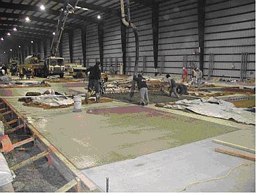
Figure 24. Second Placement of Concrete in MRG
Figure 25. Checkerboard Placement Pattern, MRG
Additional Demolition, Excavation, and Removal
An area covering stations 525 to 600 contained 20 ft. by 20 ft. by 9 3/4 in. thick concrete slabs from the original CC-1 at the NAPTF. They rested on an Econocrete subbase 6 in. thick. A single experimental concrete slab 15 ft by 15 ft by 11 in. thick rested in the area from station 542 to 557, south side. The slab was placed on June 2, 2003. It was used for corner curling studies and served as a preparatory step toward the construction and testing of the subject CC-2 test items.
A saw, equipped with rotary blades, was used to cut all of the existing concrete slabs into 5 ft. by 5 ft. sections, including the single experimental slab. They were cut to their full thickness. J.B.T. Building Co. used an excavator, equipped with a small bucket and thumb, to lift the slab sections and place them on a dump truck. The dump truck was used to remove the sections from the test site. The exposed area of the Econocrete subbase was swept clean in preparation for the placement of the forms and the installation of the instrumentation for the MRS test item. An elevation survey of the Econocrete surface was conducted by the FAA Construction Manager. Measurements were taken on a 5-ft grid.
Additionally, the asphalt layer was removed from the 3 ft shoulder on the south side, station 525 to 600. The asphalt on the north shoulder had been removed from the previous excavation (section 2.1). The underlying crushed stone base, P 209, and granular subbase, P 154, materials were lifted out from both the north and south shoulder areas, station 525 to 600. The excavation extended several inches below the top level of the Econocrete surface. The excavator and small bucket were used. A dump truck was used to transport the materials from the test site.
Effort took 4 work days.
Placement of MRS
The first set of ten concrete slabs was placed on February 24, 2004, and the second set on March 2, 2004. The 36-meter pump and overhead boom were positioned east of station 600. Activities in preparation for placement and activities during placement were similar to those performed for the construction of MRC and MRG. Some preparatory activities were different and are noted below.
Shallow grooves were saw cut in the surface of the Econocrete subbase to accommodate the placement of wires for the instrumentation system. Once the wires were placed, the grooves and wires were covered with grout, and the surface smoothed. The grout consisted of a cement based floor underlayment.
Holes were drilled in the west edge of existing transition 7 in order to receive the dowels. The 1 in. by 18 in. steel dowels were hammered into the holes forming a “pressed fit”. The dowels were located 5 in. above the Econocrete surface and spaced at 10 in. cc. These dimensions were chosen in order for the dowels to fit between the sawed ends of the existing dowels (CC-1) which remained embedded in the edge of transition 7. Adjustments were made in the spacing at the locations of what would be the new slab edges in order to allow proper clearances for the dowels with those to be placed in the slabs at right angles. A foam plastic liner, of 1/2 in. thickness, was then fitted over the dowels, flush to the west edge of transition 7. The liner allowed for future expansion of the test item. The exposed ends of the newly placed steel dowels were then covered with light grease.
Thin open areas between the base of the plywood forms and the slightly irregular surface of the Econocrete subbase were filled with sprayed-on plastic foam. Excess was trimmed flush with the sides of the forms at the interior faces. The application of plastic foam was not required in MRC or MRG where the base materials yielded under the forms, to a small degree, leaving no open areas. Strips of construction paper were placed on the Econocrete surface to act as a bond breaker between the Econocrete and the concrete slabs. United Concrete provided the concrete placement and the FAA support contractor supported the curing and control of curling. MRS was accepted by the FAA Construction Manager.
This effort took 17 work days.
An elevation survey of the surface was conducted by the FAA Construction Manager on April 27, 2004. Measurements were taken on a 5-ft grid. Final slab thicknesses were established. The survey was repeated on December 22, 2004. This last survey was conducted in order to determine the degree of settlement that may have occurred after all of the traffic testing was completed.
Placement of Transition 7 Overlay
The existing transition 7 was retained. It had been placed during the original CC-1. It was 60 ft. wide and 25 ft. long, similar to the other transitions. It extended from station 600 to 625. It was formed of concrete 9 3/4 in. thick and rested on an Econocrete subbase 12 in. thick.
The original surface of the transition was vacuum cleaned and power washed. Wood forms, in the general shape of flat studs, were placed on the north, south, and east edges. The newly placed MRS slabs, with the foam plastic expansion liner, formed the west edge. The overlay was set at about a 2 1/4 in. thickness.
The original surface of the transition was then ground, buffed, and power washed. The following day (day of placement) it was covered with an epoxy bonding coat. Reinforcement was then set on steel chairs and rested at the half thickness of the overlay. The reinforcement consisted of a mesh of 3/16 in. steel bars set to a 4 in. grid. Concrete, with a specified compressive strength of 4,500 psi, was then placed directly from the trucks which were positioned east of station 625. The mix had a course aggregate requirement of 1/2 in. maximum. Hand placement and finishing techniques were used in forming the overlay. When completed, the overlay was covered with plastic sheets.
The plastic covers were removed the following morning. Shallow soft cuts were placed in the concrete to encourage and contain joint formation. One transverse cut was made in the center of the overlay (12 ft. 6 in. from the east or west edge). Five longitudinal cuts were made, spaced at 10 ft. The surface was then vacuum cleaned and wet with a hose. It was covered with burlap strips and again wet. The entire transition was then covered with plastic sheets and left to cure for 9 days. The plastic and burlap were removed after the curing period. The surface of the transition was swept clean. The surface was then sprayed with two coats of a water based curing and sealing compound. The transition 7 overlay was accepted by the FAA Construction Manager.
The effort took 5 work days.
Sealing Joints, MRC, MRG, and MRS
Plastic sheets and burlap were temporarily removed from the surfaces of MRC, MRG, and MRS. All joints bounding the 15 ft. by 15 ft. slabs were saw cut. The saw cut grooves were 1/4 in. wide by 1/2 in. deep. The joints were then filled with a foam sealant. The excess was trimmed the following day. The joints were sealed to minimize water seepage to the supporting layers. The surfaces of the test items were then cleaned and covered with the burlap strips. They were watered using four passes of the BDF with the test vehicle running at 0.50 ft. / sec. The test items were then covered with the plastic sheets, retaining the wet surface condition.
The effort took 2 work days.
Covering Exposed Shoulders
The north and south shoulders had been excavated for the reconstruction. The reconstruction and buildup, however, did not include the shoulder areas above the level of the granular base for MRC, the subgrade for MRG, and the granular subbase for MRS. In effect, trenches of 3 ft. width and 1 to 1 1/2 ft. depth remained on the north and south sides, running from station 300 to 600. The inner boundary of the trenches was formed by the sides of the test slabs, the outer boundary by the inner side of the foundation of the rails on which the test vehicle ran. The trenches were covered with plastic sheets in order to protect the subgrade from receiving water. The plastic was held to the sides of the concrete slabs by sandwiching it between the concrete and wood studs placed longitudinally. The studs were secured to the concrete with metal fasteners.
This effort took 4 work days.
Click the links provided for additional Test Item Construction and Placement information : Concrete Record-MRC Concrete Record-MRG Concrete Record-MRS Pumping Effects CC2 Test Item Construction