Trenching
CC5 LFC 1 Post-Traffic Trenching Test Plan
Revised 1/18/10
The CC5 LFC 1 – NW, NE, SW, and SE were completed with 10 wheel loading (NE and SW) and 6 wheel loading (NW and SE). The surface transverse profiles measured by a string line at each test item show different locations of maximum depression and upheavals. The maximum depressions and upheavals would represent the points of significant pavement compressions and dispersions respectively. The locations are selected based on the acquired transverse profiles and details are presented in the attached figure 1.
This post traffic trenching test would investigate any changes of each pavement layers and the materials will be characterized.
P-401: ASPHALT CONCRETE SURFACE
- GPR and Cores: GPR will be done on the top of the proposed test locations to measure the thickness of the asphalt layer. After GPR is done, cores will also be taken so as to co-relate with the thicknesses obtained from GPR.
P-209: CRUSHED STONE BASE
After 5 inches of asphalt layer is removed, 8 inch P-209 layer will be exposed. Following tests are proposed on P-209 material.
- Nuclear Gauge Density Tests: Nuclear density gauge will be done at the proposed test locations to determine both the in-situ density as well as moisture content of the base material.
- D-PSPA Tests: These will be done at the same locations as density tests.
- LWD’s Tests: These will be done at the same locations as density tests on the top layer of P-209.
Additionally P-209 material from trenches will be collected and stored for doing resilient modulus and strength tests.
P-154: CRUSHED STONE SUBBASE
After 8 inches of P-209 layer is removed, 34 inches of P-154 layer will be exposed. Following tests are proposed on P-154 material.
· CBR Tests: These will be done at the proposed test locations on the top of the P-154 surface. Additional or fewer tests may be done if need arises
· Density Tests: Nuclear density gauge will be done at the proposed test locations to determine both the in-situ density as well as moisture content of the P-154 material. Sand cones will also be done at few of the nuclear gauge measurements locations. Additional or fewer tests may be done if need arises.
· LWD’s and D-PSPA Tests: These will be done at the same locations as density tests on the top layer of P-154.
Additionally P-154 material from trenches will be collected and stored for doing resilient modulus and strength tests.
DUPONT CLAY: SUBGRADE
Once the P-154 material is removed, the interface of P-154 and subgrade will be documented through notes and photos. Following tests are proposed on subgrade material.
- CBR Tests: These will be done at the proposed test locations on the top layer of subgrade material. CBR’s on the lower lifts will be fewer in number and locations will be based on judgement. The thickness of the subgrade material removed will be same as the thickness of that particular lift during construction.
- Density Tests: These will be done at the same locations as CBR tests.
- Vane Shear Tests: These will be done at the same locations as CBR tests.
- LWD’s & D-PSPA Tests: These will also be done at the same locations as CBR tests.
- Shelby Tube Samples: These will be taken at 6-8 locations (to be decided later) to perform resilient modulus and unconfined compressive tests on samples from these tubes.
- Profile Measurements: These will be done along one face of each trench to measure the profile of each layer of the pavement.
COUNTY SAND AND STONE: SUBGRADE
Surface of County Sand and Stone which is located at approximately 6.5 feet below the pavement surface will be exposed and tested. Same tests will be performed as for DuPont Clay as described above.
PROFILING
Transverse profiles will be taken at each exposed layers using a string line at surfaces of P-401, P-209, P-154, DuPont Subgrade, and County Sand and Stone.
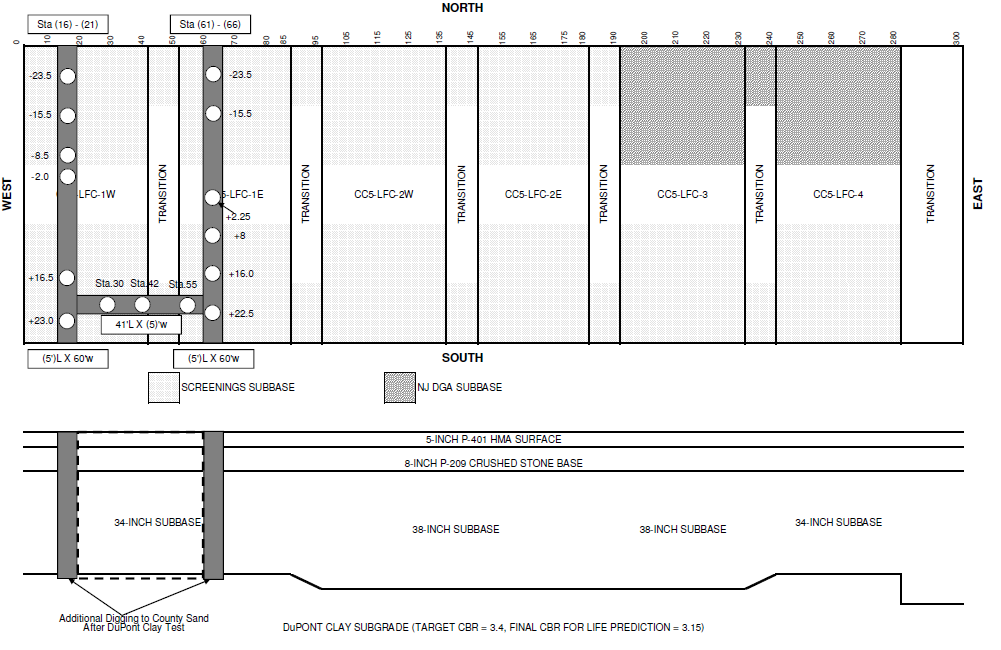
Figure 1: Trench Locations and Proposed Test Locations (test locations are based on P-401 profiles; it may be different for sublayers).
Trenching-Layout and Test Locations-CC5 09-08-10.xls