OVERVIEW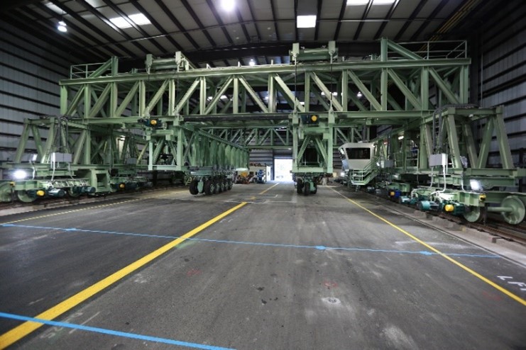
This test area within the NAPTF uses a rail-based test vehicle that can simulate the heaviest aircraft found in commercial fleets.
The test track the vehicle runs on is 900 ft. long by 60 ft. wide (274 meters long by 18 meters wide) and is comprised of independently constructed test items. Asphalt and concrete pavements are embedded with hundreds of sensors throughout the track and are subjected to simulated aircraft traffic, enabling researchers to collect high quality, accelerated test data through a fully automated computerized data acquisition system.
With the capability to construct individualized test items, ATR engineers can run multiple projects concurrently on the test track. The test items also reflect the various land types airports are built on, and their geological composition can be individually altered. For example, to simulate pavement integrity at airports built on former wetlands, ATR engineers construct sections of pavement on a saturated clay bed for the vehicle to run on.
Each time a new section of runway is built (approximately 300 feet/91 meters), it is called a Construction Cycle (CC).
CONSTRUCTION CYCLE DETAILS
See the Construction Cycle Database at the end of this page for detailed information.
Each test item is constructed to meet one of the three subgrade classifications: low strength, medium strength, and high strength. Each test item is trafficked to ‘failure’ by the NAPTV and then reconstructed.
The timeline for a construction cycle is 2-3 years and includes the construction of the test pavement, installation of embedded pavement sensors, traffic testing to failure, post-traffic testing (trenching activities and other tests), and pavement removal.
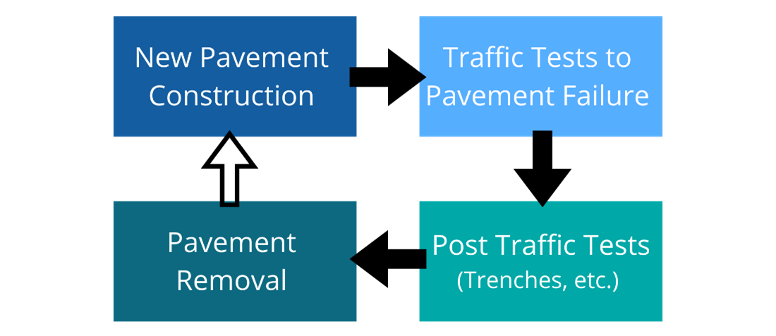
Figure 1. Overview of a Construction Cycle
Data gathered from the NAPTV research is organized and archived by construction cycle, with each construction cycle having its own database. To gather data, the test track is embedded with hundreds of sensors. The sensors are one of two types: static or dynamic. Static sensors monitor temperature, moisture, and crack status (resistance) on an hourly basis. Dynamic sensors are automatically triggered by NAPTV operations and measure quantities such as strain and pavement deflection in response to the load. Learn more about the NAPTV.
|
Static Sensors
|
|
Air Relative Humidity & Temperature Sensor, Humidity Gages, Moisture Sensors, Relative Humidity Sensor, Resistance Gages, Specific Heat Sensor, Temperature Gages, Thermistor, Thermocouple
|
|
Dynamic Sensors
|
|
Asphalt Strain Gages (ASG), Compression Gages, Concrete Strain Gages (CSG), Eddy Current Sensor, Fiber Optic Strain Gages, Horizontal Displacement Transducer, Joint Clip Gage, Linear Position Transducer, Multi-Depth Deflectometers (MDD), PCC Strain Gage Joint Gages, Potentiometer, Pressure Cells, Soil Pressure Cells (SPC), Vertical Displacement Transducer
|
|
Other Sensors
|
|
Bender Element, Coil Sensors, Coda Wave Interferometry Sensor, Fiber Optic Strain Plate, Ovalization Sensor, Piezo-electric Energy Accumulator, Smart Rock, Ultrasonic Crack Sensing Sensor
|
Table 1. Examples of Sensors used at NAPTF
The FAA has completed nine construction cycles since opening the NAPTF in 1999. Each construction cycle database is accessible to FAA personnel and public researchers. See the Construction Cycle Database at the end of this page for a summary of each construction cycle and links to the databases.
ADDITIONAL INFORMATION ON CONSTRUCTION CYCLES (CC)
Test Item Designations
Each test item is designated by its construction cycle number and three characters*. The first character denotes the subgrade strength (L – Low, M – Medium, H – High). The second character indicates the type of pavement (F – Flexible [asphalt], R – Rigid [concrete]) and the third character denotes the base type (S – Stabilized, C – Conventional, G – Grade).
Example: CC3, LFC refers to low-strength subgrade flexible pavement with conventional base constructed during construction cycle 3.
*The test item designations used during CC4 and CC8 vary from the standard format. CC4 designations indicate the test section side (N – north, S – south) and panel number (i.e., 1N-3). CC8 designations indicate the test type (O – overlay, JC – joint compression, SF – strength/fatigue), test section side (N – north, S – south), and panel number (i.e., ON5).
Coordinate System and Sign Conventions
The pavement test items, sensor locations, and position of the NAPTV load modules, are oriented in an east/west direction. An X, Y, Z coordinate system, applicable to all construction cycles, is used to uniquely identify the location of each of those items. All coordinates in the NAPTF are measured off established benchmarks set by professional surveyors. The origin point for the coordinate system is the centerline of the pavement surface at the west end (low-strength) of the NAPTF.
Longitudinal Coordinates (X): The longitudinal coordinate X = 0 starts on the west end pavement centerline and increases to X = 900 feet (274 meters) on the east end of the NAPTF.
Transverse Coordinates (Y): Transverse distances are measured relative to the centerline. Positive Y coordinates increase to the south to Y = 33 feet (10 meters), and negative coordinates increase to the north to Y = -33 feet (-33 meters).
Vertical Coordinates (Z): Vertical locations are measured from the top of the original pavement surface. The Z coordinate is positive downward (instrumentation in an overlay would reflect a negative Z coordinate).
Sensors
Each construction cycle uses a variety of sensors to capture data based on the testing objectives. Data from static sensors is commonly collected on an hourly basis using a data logger. Dynamic sensor data is collected during traffic testing and monitoring of the construction cycle.
The NAPTV triggers the dynamic sensor data loggers during traffic testing. This enables synchronization of the NAPTV load data files with the dynamic sensor data files. Sensor data for each construction cycle is available in the construction cycle databases (see table at the bottom of page).
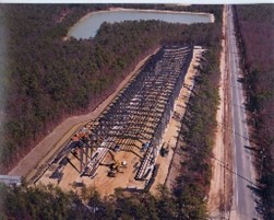
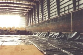
Original Construction
The below images show the original construction of the National Airport Pavement Test Facility (NAPTF) and Construction Cycle 1 (CC1).
|
|
|
|
|
|
|
1. Aerial view of NAPTF facility under construction.
|
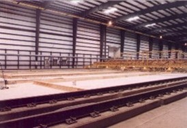
2. 20 mil membrane on the floor of the low-strength subgrade.
|
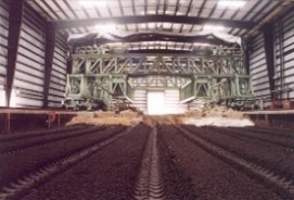
3. View of the test vehicle from the top of the low-strength subgrade. The soil is drying after being tilled.
|
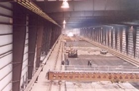
4. Forms being prepared for P-501 Placement. View of deck finisher in the background.
|
5. Start of asphalt paving. View from the top of vehicle.
Beam in foreground was used to support the CBR measurement equipment and a water spray bar.
|
CONSTRUCTION CYCLE (CC) DATABASES
The below table provides a summary of each construction cycle and links to the associated database. Click on the links to access the construction cycle database.
|
Construction Cycle
|
Classification (Rigid/Flexible)
|
Objectives
|
|
Construction Cycle 1
|
Both
|
1. Provide full-scale test data to support the new computer-based design procedures that were under development by the FAA.
2. Provide full-scale pavement response data for use in airplane landing gear design and configuration studies; and
3. Provide full-scale test data for re-evaluation of the load repetition (alpha) factors used in the CBR method of design for flexible pavements.
|
|
Construction Cycle 2
|
Rigid
|
The main objectives were divided up into 5 different experiments:
1. CC2 Test Strip: Intended to study the effects of slab size and mix design on pavement curling during the early age of the concrete.
2. CC2 Single Slab: Intended to provide experience for the design, placement, and monitoring of the actual PCC test items.
3. CC2 Twin Slab: Intended to compare the behavior of the slab with no fly ash content to the behavior of a companion slab with high fly ash content.
4. CC2 Test items: Designed and constructed to compare the performance of three types of rigid pavements: concrete slabs on stabilized bases (MRS), concrete slabs on aggregate bases (MRC), and concrete slabs placed directly on subgrade (MRG).
5. CC2 HMA Overlay: The three rigid airport pavement test items (MRC, MRG, and MRS), built as CC2 main test items at the FAA National Airport Pavement Test Facility (NAPTF) with 12-inch thick concrete slabs on different support systems, were rubblized with a resonant pavement breaker and overlaid with five inches of P-401 hot mix asphalt (HMA). The overlaid pavements were subjected to full-scale accelerated traffic loading to observe the changes in the modulus of the rubblized concrete layer.
|
|
Construction Cycle 3
|
Flexible
|
Provide full-scale test data to improve FAA thickness design procedures for flexible pavements supporting 4-wheel and 6-wheel aircraft gears.
|
|
Construction Cycle 4
|
Rigid
|
Improve the understanding of the influence of design parameters on unbonded concrete overlays of rigid airfield pavements, thus enabling improvement of FAA design methods.
|
|
Construction Cycle 5
|
Flexible
|
1. Produce data on the relative performance of flexible pavements supporting simple 6-wheel and 4-wheel gears, versus large gear assemblies consisting of multiple 6- and 4- wheel landing gears in close proximity.
2. Produce data on the effect of increased tire pressure above 214 psi (1.475 MPa)
|
|
Construction Cycle 6
|
Rigid
|
The primary objective was to determine the effect of concrete flexural strength ranging from 500 to 1000 psi (3.447 MPa to 6.894 MPa on rigid pavement structural life.
|
|
Construction Cycle 7
|
Flexible
|
The main objectives were divided into 2 different experiments:
1. CC7 North: Perpetual Pavement Testing to extend the Perpetual Pavement concept to airport pavements.
2. CC7 South: Overload Testing to determine allowable overload criteria (per ICAO Annex 14) for flexible pavements.
|
|
Construction Cycle 8
|
Rigid
|
Phase 1 Overload: To develop rational overload criteria (per ICAO Annex 14) for rigid pavements.
Phase 2 Overlay: To test the performance of a PCC overlay on an existing PCC with Structural Condition Index (SCI) in the 50-80 range.
Phase 3 Joint Comparison: To compare the performance of Type E (doweled construction) and nonstandard sinusoidal keyed longitudinal joints.
Phase 4 Strength & Fatigue: To obtain slab strength (rupture strength) for full-scale slabs under a monotonically increasing aircraft gear load, as well as the fatigue strength of rigid pavement slabs under non-wandered traffic.
|
|
Construction Cycle 9
|
Flexible
|
The main objectives were divided up into 3 different experiments:
1. HMA Fatigue Model and Base Thickness: To verify, refine, or modify the FAARFIELD HMA fatigue model.
2. Cement-Treated Permeable Base (CTPB): To evaluate the performance of a CTPB course compared to a standard crushed aggregate base course.
3. Overload: Phase 2 research based on Construction Cycle 7 (CC7). Data from CC9 will further the findings from CC7 and support the development of strain criterion (per ICAO Annex 14) for allowable overload in flexible airport pavements.
|