Dynamic Sensor Data
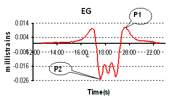
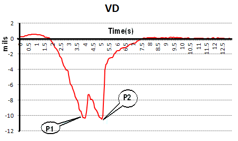
Contains dynamic sensor responses, including peak values and full dynamic records. Fields are defined in the following list. The following figure illustrates properties of the sensor record as given in the Dynamic_data table.

Definition of Fields in Table Dynamic_data
|
SensorID
|
Number assigned to an individual sensor in the "SPU" table.
|
|
EventNo
|
Number assigned to an event in the “Traffic” table. An event is defined as a vehicle movement with loads.
|
|
StartTime_S
|
Time after the start of an event corresponding to the first data sample added to the SensorRecord (seconds).
|
|
StartVehiclePosition_FT
|
The vehicle position corresponding to time StartTime (feet).
|
|
EndTime_S
|
Time after the start of an event corresponding to the last data sample added to the SensorRecord (seconds).
|
|
EndVehiclePosition_FT
|
The vehicle position corresponding to time EndTime (feet).
|
|
OffsetLeft
|
Average value of the sensor reading prior to the initial load response (sensor units).
|
|
OffsetRight
|
Average value of the sensor reading following the load response (sensor units).
|
|
FilterFreq_HZ
|
Frequency of the applied data filter (Hz).
|
|
Peak1Time_S
|
Time after the start of an event corresponding to Peak 1 (seconds). See below for information on how Peak1 and Peak2 are determined.
|
|
Peak1
|
Value of Peak 1 relative to OffsetRight (sensor units). See below for information on how Peak1 and Peak2 are determined.
|
|
Peak2Time_S
|
Time after the start of an event corresponding to Peak 2 (seconds). See below for information on how Peak1 and Peak2 are determined.
|
|
Peak2
|
Value of Peak 2 relative to OffsetRight (sensor units). See below for information on how Peak1 and Peak2 are determined.
|
|
Peak3Time_S
|
Time after the start of an event corresponding to Peak 3 (seconds). See below for information on how Peak1 and Peak2 are determined.
|
|
Peak3
|
Value of Peak 3 relative to OffsetRight (sensor units). See below for information on how Peak1 and Peak2 are determined.
|
|
SamplePeriod
|
Sampling rate for the signal (seconds). Note: The sampling rate for all CC6 dynamic data records is 0.05s.
|
|
SampleCount
|
Number of samples in a record.
|
|
SensorRecord
|
Full dynamic sensor data corresponding to an event, consisting of a string of SampleCount values delineated by commas (sensor units).
|
|
SpuRefTime
|
Date/Time when the sensor record was recorded by the signal processing unit (SPU). Date is recorded as MM/DD/YYYY. Time is local time (New Jersey, USA).
|
|
modified
|
|
|
Comments
|
|
Determination of Peak1 and Peak2 in Dynamic Data Records
|
Embedded Strain Gage (EG)
|

For Embedded Strain Gages (EG), Peak1 is defined as the maximum strain value in a sensor record. Peak2 is defined as the minimum strain value in the same record. Thus, the value of Peak1 is always positive (tensile strain), while the value of Peak2 is always negative (compressive strain). For a record with tensile strain only, the value of Peak2 will be zero, and the corresponding Peak2Time will also be recorded as zero. Likewise, for a record with compressive strain only, the value of Peak1 will be zero. Note that this definition does not capture every peak in a typical strain response, so in the case of multiple peaks due to tandem wheel loads, it is recommended to examine the sensor record.
|
|
Vertical Displacement Transducer (VD) and Pressure Cell (PC)
|

For dynamic sensors other than EGs, Peak1 is the value of the first peak that is encountered in a sensor record. Peak2 is the value of the second peak. Peaks may be either positive or negative. Note that since Peak1 and Peak2 are determined by the time sequence, the absolute value of Peak2 may be greater than that of Peak1.
|