CC2 HMA Overlay Pavement Construction/Cross Section
Pavement Structures
Three rigid pavement test items were constructed and tested during construction cycle two (CC2) at the NAPTF. Each test item was 75 feet long by 60 feet wide (22.9 m by 18.3 m) with thirty 15 by 15 foot by 12-inch thick concrete slabs (4.57 m by 4.57 m by 30.5 cm). One of the test items (MRG) was built directly on the subgrade, the second (MRC) was built on a crushed aggregate subbase on top of the subgrade, and the third (MRS) was built on an econocrete subbase over a crushed aggregate lower subbase. Each test item was separated into two 30-foot (9-m) wide traffic lanes, north and south. Construction was completed in April, 2004, and traffic testing was completed in December, 2004.
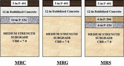
Figure 1. CC2-Overlay Pavement Test Sections.
Posttraffic testing included the excavation of four test pits, approximately five feet wide by five feet long, and extending down into the subgrade. One test pit was opened in the south traffic lane of each test item and one opened in the north traffic lane of MRC. Detailed information on the design and construction characteristics of the pavement structures can be found in (Ricalde). The structural condition index (SCI) of all the rigid pavement test items, in both traffic lanes, was less than 20 at the end of trafficking. However, most of the cracks were tight, with none rated worse than low severity. Also, both the transverse and the longitudinal joints were formed and doweled.
In January, 2005, all of the concrete slabs in the north traffic lane, including those in the transition sections, were rubblized with an RMI RB-500 resonant breaker operating at 44 Hz. Then, in June, 2005, the rubblized pavement was lightly wetted, rolled with a vibratory steel drum roller, and overlaid with five inches of P-401 hot mix asphalt (See Figure 1). Figures 2 through 5 show, respectively, the vibrating foot of the resonant breaker, the rubblized surface being rolled, the test pavement surface after rubblization, and the test pavement surface after overlaying (with the HWD equipment in position for uniformity testing).
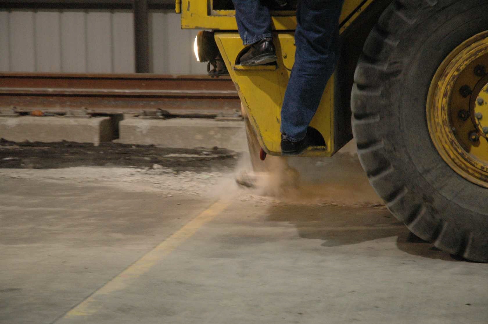
Figure 2. Rubblizing the north traffic lane pavement.
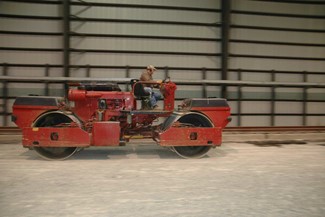
Figure 3. Rolling the rubblized with the resonant breaker.
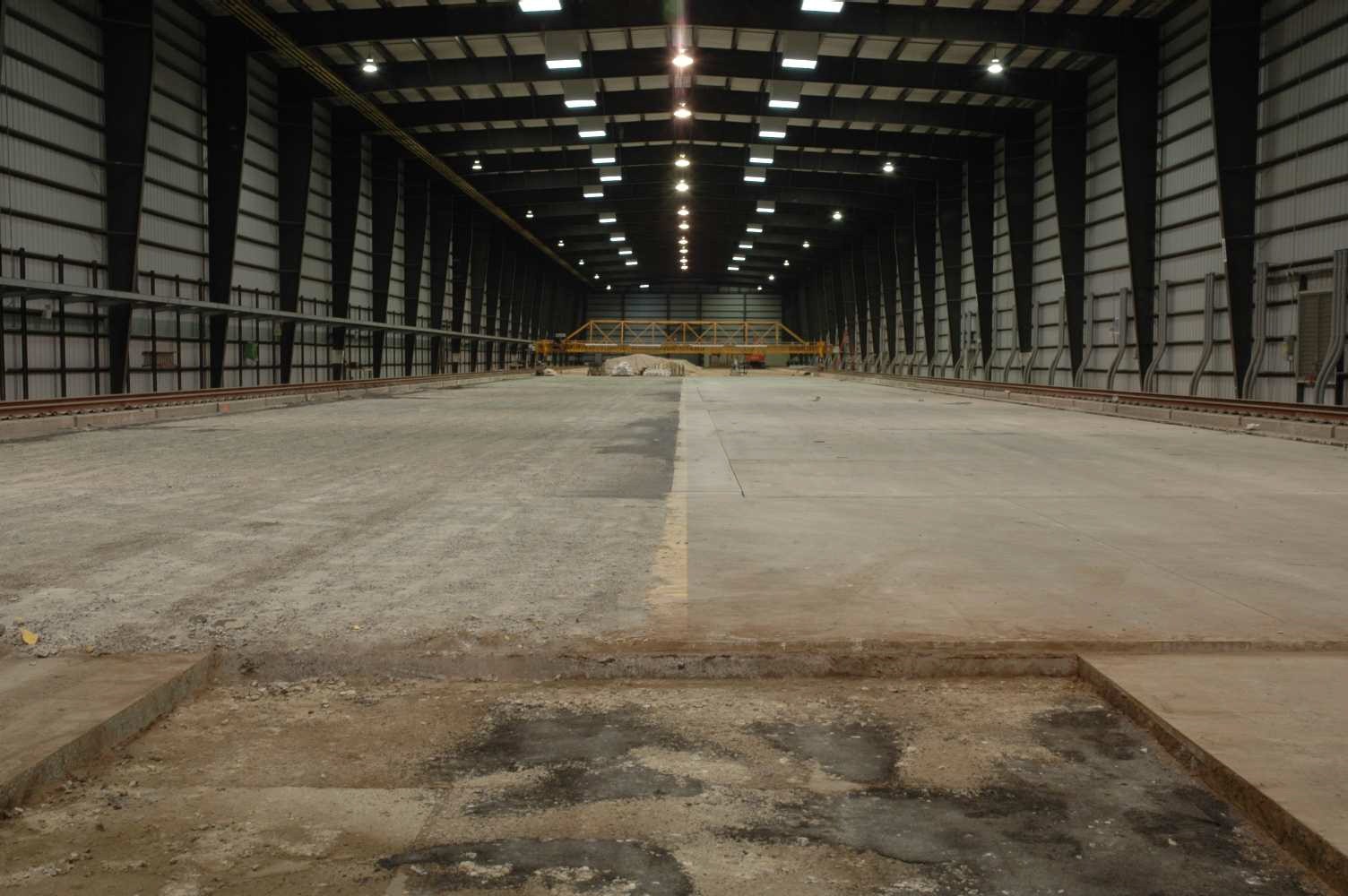
Figure 4. Rubblized on the left (north) on the right (south).
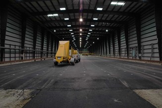
Figure 5. After asphalt overlay, with as-trafficked HWD equipment in foreground.