CC4 Pavement Construction/Cross-Section (con.)
Figure 1 shows the three structural cross-sections, numbered 1, 2, and 3 from west to east. The relative thicknesses were designed to encompass most unbonded overlay thickness to existing underlying pavement thickness configurations found in practice, while still having absolute thicknesses that could be accommodated within the testing bed.
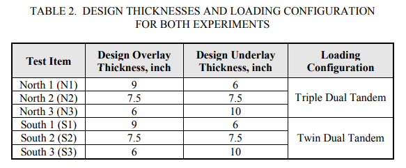
Figure 2 shows the transverse cross-sections, indicating that each structural cross-section has two 12.5-ft wide lanes, with a 10-ft transition slab between the test items. The slabs in the north lane were loaded with a triple dual tandem gear, while the slabs in the south lane were loaded with a twin dual tandem gear. The resulting six test items are summarized in table 2.

Joint patterns were established to create matched and mismatched transverse joints in the underlying slab and the concrete overlay as shown in figure 1. All longitudinal joints were mismatched or offset as shown in figure 2. The underlay joints were sawcut and not doweled. The overlay joints were all doweled and sawcut, both in a transverse and longitudinal manner. As discussed in a later section, the structural cross-section was loaded alternately from west to 6 east and east to west. The loading direction may affect responses of both the pavement and instrumentation, so the relative position of joint offset is illustrated.