Gear Configuration
The figure below shows the gear load configuration for the rigid pavement traffic test. The north carriage (left) was configured to represent a B777 main gear. The south carriage (right) was configured to represent one truck of a B747 main gear. The 54-inch dual spacing at the north carriage deviates slightly from the actual dual spacing of a B777 main gear truck (which is 55 inches) due to the fixed spacing positions available on the NAPTF wheel modulus.
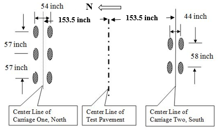
Gear Configurations (Click to Zoom)
Wheel Loads/Tire Pressure
Wheel loads are provided by hydraulic actuators reacting against the dead weight of the vehicle. Slow rolling tests were performed during August to September 1999. In these tests, the testing vehicle was rolled at a speed of 0.5 ft. /sec (0.15 m/sec) with 12,000 lbs. (53.4 kN) and 24,000 lbs. (106.8 kN) wheel loads for rigid pavements and 24,000 lbs. (106.8 kN), 30,000 lbs. (133.5 kN) and 36,000 lbs. (160.1 kN) wheel loads for flexible pavements. Loads were selected such to minimize pavement damage.
For traffic testing, wheel loads were set at 45,000 lbs. (20.4 tonnes) with a target tire pressure of 188 psi (1295 kPa). The vehicle speed was 5 mph (8 km/h) during testing.
Wander Pattern
The wander pattern consists of a fixed sequence of 66 vehicle passes (33 in the east to west and 33 in the west to east). The 66 passes were arranged in nine equally spaced wander positions at intervals of 10.25 inches (260 mm), shown in the figures below. The last figure shows the number of repetitions at each wander position in a complete wander cycle. The wander pattern was intended to approximate a normal distribution of aircraft traffic with a “wander width” of 70 inches.
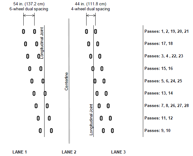
6-Wheel and 4-Wheel Wander Patterns (Click to Zoom)
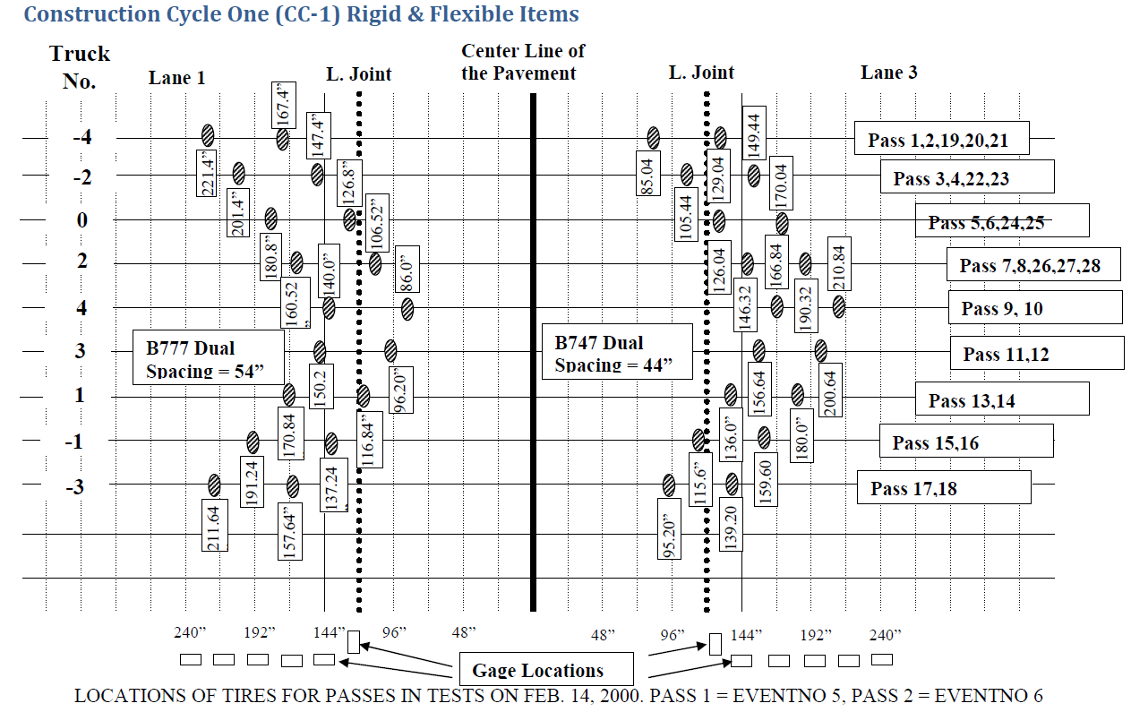
6-Wheel and 4-Wheel Wander Patterns with Offsets (Click to Zoom)
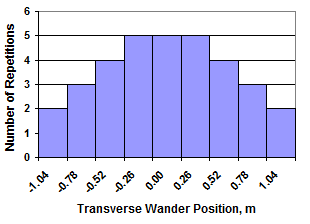
Wander Distribution (Click to Zoom)
Return to Construction Cycle 1 Main Page