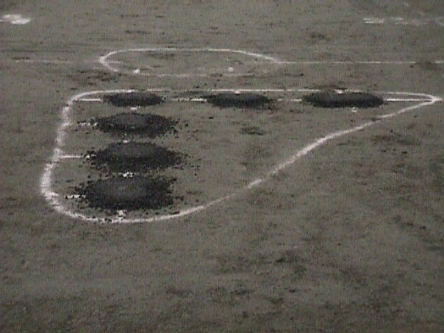
Multi-Depth Deflectometer (MDD)
MDDs, manufactured by Construction Technology Laboratories (CTL), were used to measure deflections of pavement layers at multiple vertical locations referenced to a stable point. Each MDD is an array of seven potentiometer Displacement Transducer (DT) placed at strategic locations to capture the multiple-wheel load interaction (figure below). The MDDs were anchored at a depth where no significant displacement was expected. The surface DT measured displacements relative to the anchor whereas the other DTs measured displacements relative to the surface layer. Thus, placements at specific depths were obtained by subtracting the specific depth DT response from the surface DT response.
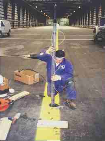
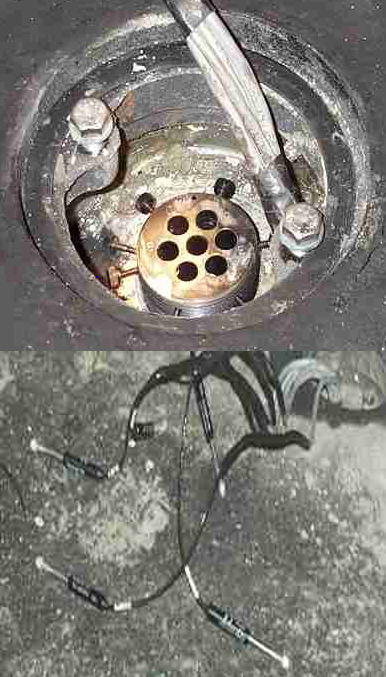
Installation of Multi-Depth Deflectometer (MDD) (Garg 2003) (Click to Zoom)
Return to Construction Cycle 1 Instrumentation Plan
Asphalt Strain Gauge (ASG)
The exposure to the high temperature accompanying rolling and vibratory impacts during and after installation reduces the survival rate of these gauges, making it difficult to install these sensors. To ensure a high survival rate, manufacturers developed a robust sensor combined with installation procedures that increased gauge survival rates (Weinmann et al. 2004). The ASGs were fabricated by CTL and were applied on 0.31 inches (0.79 cm) diameter and 8 inches (20.3 cm) long polyester bars at mid length between end flanges. A schematic showing details of the principal features of the design and construction of the ASGs is shown in the figure below (Garg and Hayhoe 2001). According to manufacturer specifications, the ASG instrument had an accuracy of 1 microstrain and a resolution of 0.1 microstrain. The measurement range was 2000 microstrain and the temperature range was from 0 to 150°C.
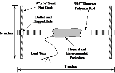
Asphalt Concrete Strain Gauge (Garg and Hayhoe 2001) (Click to Zoom)
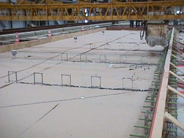
ASGs were installed in both longitudinal and transverse directions at the bottom of the surface asphalt layer and at the bottom of the stabilized base asphalt layer of the stabilized base test items. The figure below shows the installation of ASG in the AC layer. A total of 96 H-bar type ASGs (transverse and longitudinal) were installed at the time of construction. The location of the ASGs in flexible test itemns are presented by CTL (1998).
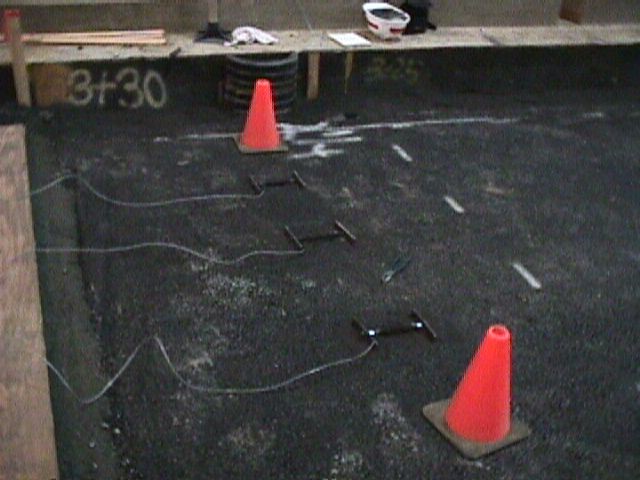
ASG Installation (Click to Zoom)
Return to Construction Cycle 1 Instrumentation Plan
Concrete Strain Gauge (CSG)
CSGs were of the same basic design as the ASGs, except that the foil gauges were affixed to 0.31 inch diameter (0.79 cm) and 8 inch long (20.3 cm) steel bars. Only slabs 2 and 3 in each lane were instrumented. Sensors were installed near both the top and bottom surfaces of the slabs to provide measurements of the tensile and the compressive strains that developed during loading. The photos below show the installation of CSGs in the NAPTF rigid pavement test items. A total of 154 concrete strain gauges were installed in test items LRS, MRS, and HRS. From the total of 154 concrete strain gauges, 40 were found to be not performing, including 14 sensors (9.1%) in LRS, 12 sensors (7.7%) in MRS and 14 sensors (9.1%) in HRS (Guo, Hayhoe et al. 2002) The details about the location of the sensors are documented by Guo, Hayhoe et al. (2002).
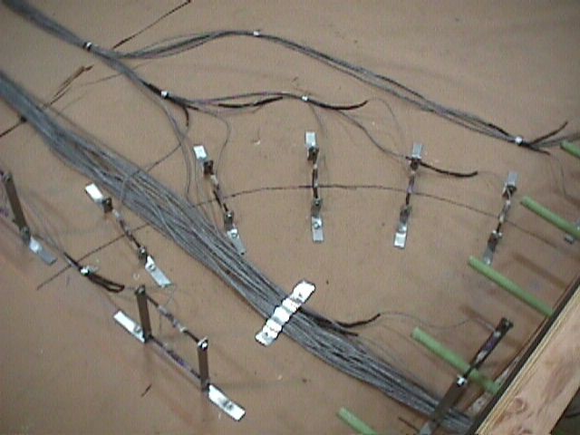
CSG Installation (Click to Zoom)
Return to Construction Cycle 1 Instrumentation Plan
Pressure Cell (PC)
A total of 60 PC6 and 84 PC2 pressure cells were installed to measure pressures. The PC2 were Kulite Model Soil Pressure Cells. They were small diameter soil pressure cells consisting of a liquid-filled hollow steel cell of approximately 2 inches (5.1 cm) in diameter and 0.5 inches (1.3 cm) thick with an electrical pressure transducer housed within the cell. The PC6 were Geokon Model Earth Pressure Cells. They were large diameter soil pressure cells consisting of two welded steel plates of 6 inches (15.3 cm) diameter and 0.5 inches (1.3 cm) thick. The space between the two plates were filled with liquid connected to an electrical pressure transducer with a steel tube. Any change in the soil pressure where the cell was embedded, was measured by pressure transducer (CTL 1998). The PC6 sensors were installed in the unbound granular base and subbase and the PC2 sensors were installed in the subgrade. All the pressure cells were located near the west side MDDs. The 6-inch pressure cell is displayed in the figure below.
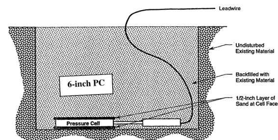
6-inch Pressure Cell (Click to Zoom)
Return to Construction Cycle 1 Instrumentation Plan