CC1 Post Traffic Testing
The objectives of post-traffic tests were to:
- Document the failure mechanism;
- And to assign post-failure properties to each pavement layer.
Post trafficking was performed on exposed test pits and trenches at different locations. Where trenches were exposed, they extended the full width of the test item from north to south. Test pits covered a smaller area of approximately 4 ft. by 4 ft.
Post-traffic testing was only performed on the flexible test items. The post-traffic tests on the rigid pavement test items were performed as part of Construction Cycle 2 (CC2).
Characterization tests conducted at the top of each exposed layer typically included:
- CBR,
- Dynamic cone penetration (DCP);
- And in-situ density.
Samples were removed to perform lab characterization tests including resilient modulus and moisture content.
A summary of summary of post-traffic tests performed on each test item can be seen in the table below.
*LFC-E, LFS-E and MFS-E in the table stands for the trench dug at the East MDD location.
*LFS-W, MFC-W and MFS-W stands for the trench dug at the West MDD location.
|
Trench ID
|
Material
|
Test
|
No. of Samples
|
|
LFS-W
|
P-209
|
Sand Cone
|
2
|
|
Subgrade
|
DCP
|
0
|
|
Subgrade
|
CBR
|
27
|
|
LFS-E
|
P-209
|
Sand Cone
|
4
|
|
Subgrade
|
DCP
|
0
|
|
Subgrade
|
CBR
|
123
|
|
Subgrade
|
Drive Cylinder
|
31
|
|
LFC-E
|
P-209
|
Sand Cone
|
5
|
|
P-154
|
Sand Cone
|
5
|
|
P-154
|
CBR
|
5
|
|
P-154
|
DCP
|
3
|
|
Subgrade
|
DCP
|
11
|
|
Subgrade
|
CBR
|
120
|
|
Subgrade
|
Drive Cylinder
|
31
|
|
MFC-W
|
P-209
|
Sand Cone
|
5
|
|
P-154
|
Sand Cone
|
5
|
|
P-154
|
CBR
|
5
|
|
P-154
|
DCP
|
5
|
|
Subgrade
|
DCP
|
16
|
|
Subgrade
|
CBR
|
105
|
|
Subgrade
|
Drive Cylinder
|
30
|
|
MFS-W
|
P-209
|
Sand Cone
|
5
|
|
Subgrade
|
DCP
|
13
|
|
Subgrade
|
CBR
|
102
|
|
Subgrade
|
Drive Cylinder
|
33
|
|
MFS-E
|
P-209
|
Sand Cone
|
5
|
|
Subgrade
|
DCP
|
17
|
|
Subgrade
|
CBR
|
132
|
|
Subgrade
|
Drive Cylinder
|
33
|
|
|
|
Total No. of Tests
|
878
|
Summary of Post Trafficking Tests Performed
For information on the Post Traffic Testing on the CC1 Experiment click on the links in the table below.
Trenching
Trenching involved removal of the AC, base and subbase layers to reveal the subgrade interface and subsequent layers below. The final trench dimensions were 60 ft. (18.3 m) long across the width of the test pavement, 4 ft. (1.22 m) wide, and 4 ft. (1.22 m) deep.
Pavement layer profile measurements were collected to measure the contribution of each component layer to the total pavement rutting and upheaval. For layer profile measurements, a string line was run at the pavement surface from south to north along the west face of the trench. The vertical distances between the string line and P-401 top (D1), P-401 bottom (D2), P-209 bottom (D3), and bottom of P-154 (D4) at 1ft. (maximum) intervals were measured as seen in the figure below.
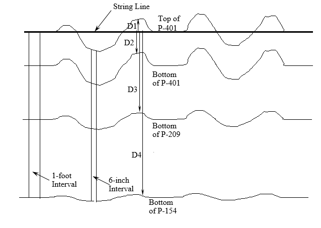
Profile Measurements on the Trench Wall (Click to Zoom)
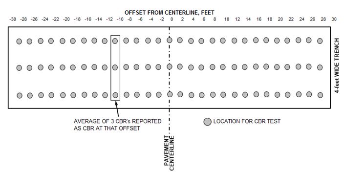
The CBR tests were performed at 2 ft. (0.6 m) intervals along the length of the trench with three penetrations for each CBR test as shown in the figure below. The minimum spacing of 12 inches (30 cm) between the adjacent penetrations was used. Moisture content was measured from the middle penetration of the CBR test samples.
CBR Test Locations at the Subgrade Surface (Click to Zoom)
Test Pit
To conduct characterization tests, test pits were excavated at various locations along CC1. The surface area for each of the 6 trenches was divided into five areas as seen in the figure below. Five test pits with an area of approximately 4 ft. by 4 ft. were excavated in each layer of the trafficked and centerline areas (one in each trafficked area (area 2 and 4), one on the pavement centerline and two outside the wander path (area 3)). Characterization tests such as CBR, dynamic cone penetration (DCP), and in-situ density were conducted on top of each exposed layer.
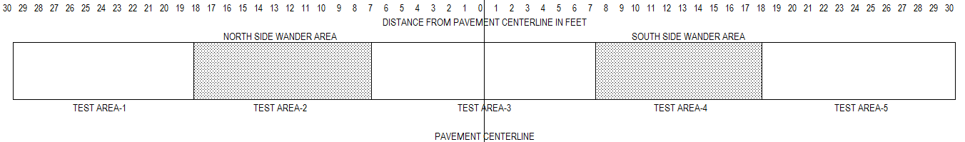
Schematic of Testing Areas (Click to Zoom)
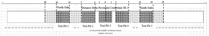
Location of Test Pits in Each Area (Click to Zoom)
Test pits were initially excavated from P-401 AC surface before the removal of layer for the trench, to expose the surface of P-209 base. In-situ density measurements were made using the sand replacement method (ASTM D4914-89) to characterize density changes from the location of maximum rutting (center of each wander path) to the location of maximum upheaval (outside the wander path) and were also compared to the density of the non-trafficked area (pavement centerline).
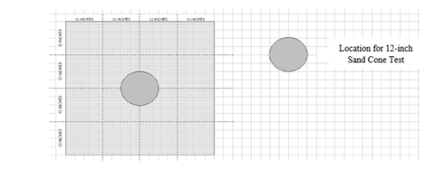
Location of 12-inch Sand Cone Density Tests in P-209 Crushed Stone Base (Click to Zoom)
After finishing the testing on the base layer, test pits were excavated at the same location from the P-209 base to expose the surface of the P-154 subbase. CBR, sand cone and DCP tests were conducted on locations inside the test pits as shown in the figure below.
Each CBR test consisted of three penetrations. Moisture samples were taken from the middle penetration of the CBR test. In situ density was measured using the sand cone method (ASTM D 1556-90). DCP tests were performed in the diagonally opposite corners inside the test pit. A total of ten DCP tests were performed in each trench testing area using disposable cones. The order in which the tests were performed was the CBR tests, followed by the sand cone, and then the DCP tests.
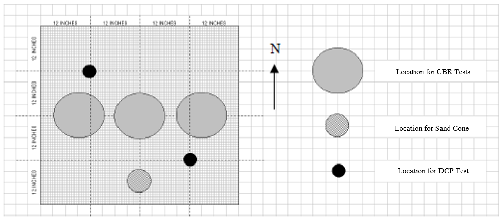
Schematic of Test Locations on P-154 in Test Pits (Click to Zoom)
Location of DCP Tests on P-154 Layer (Click to Zoom)
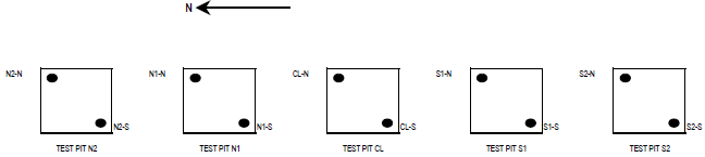
The P-154 subbase was then excavated using a backhoe. After testing on the subgrade surface was completed, test pits were dug and testing was performed at 6-inch (15 cm) depth intervals. The DCP tests were performed on the surface of the subgrade and at 24 inches (610 mm) below the surface of the subgrade. The test locations within the test pits in the subgrade are shown below. Thin-walled Shelby tube samples (ASTM D 1587-94) were stored and used for resilient modulus testing.
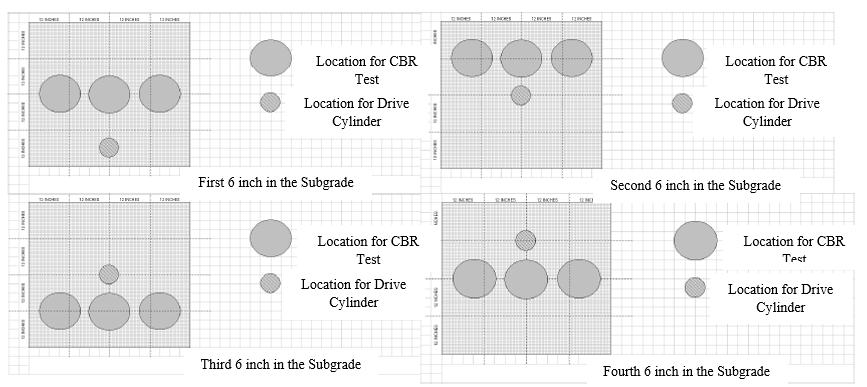
Test Locations within Test Pit in Subgrade (Click to Zoom)
Coring
Cores were obtained from the north wheel track, south wheel track and the centerline in locations with the most severe cracks, hairline cracks and medium intensity cracks. The number of extracted cores was selected based on examining the trafficked area in the two traffic lanes. The thickness of pavement component layers was measured from the cores. The cores were also inspected for separation at the interface of lifts and the depth of the cracks occurring in the pavement.
For results of each specific test item, refer to the CC1 Comprehensive Report.
Conclusions
Based on the results of the CC1 Post Traffic Testing, the key finds were:
- Overall all the cracks in the flexible pavement test items were top-down cracks and most appeared in the longitudinal direction parallel to the centerline of the pavement.
- Test items with low strength subgrade, failed at surface layers as exhibited by formation of cracks.
- In both of the low strength test items, rutting was observed in the P-401 AC layer in both traffic paths.
- Shoving occurred in the P-401 AC layer resulting in upheaval outside the traffic path.
- Lower moisture content was detected in the wheel paths compared to the outside wheel path areas.
- Failure in MFC was caused by the shear failure in the subgrade and P-154 subbase.
- Profiles showed intrusion of the subgrade material into the P-154 subbase in both traffic paths.
- Rutting was primarily contributed by the subgrade and the P-154 subbase.
- Excavated cores showed delamination between the two lifts of P-401 AC layer.
- In the MFS west trench, localized failure was observed in the 6-wheel load path where the subgrade intruded into the P-209 subbase resulting in upheaval.
- In the MFS east trench, significant rutting and AC cracking was observed in the 4-wheel traffic lane.
- From the CBR testing on the subgrade, non-trafficked area and 4-wheel traffic path had approximately similar values whereas for 6-wheel traffic path, decreases in CBR values were observed as a result of failure in the subgrade.
To be directed to the CC1 Database, click here.
Return to Construction Cycle 1 Overview