CC1 Traffic Test
Two separate test protocols were established during the first year of testing in CC1; response testing and traffic testing (trafficking). The response testing consisted of a series of static load, slow rolling and heavy weight deflectometer (HWD) testing conducted from August to September 1999.
The objectives of response testing were:
- Determine the effects of static and moving load on pavement responses.
- Determine wheel load interaction effects for different wheel and gear spacing.
The objective of traffic testing was:
- Determine the effect of gear configuration, load level and wander on pavement life.
For more information on the CC1 Traffic Test click on the links in the table below.
To be directed to the CC1 Comprehensive Report, click here.
Gear Configuration
For the CC1 Experiment test items were loaded simultaneously with two gear configurations; a 6-wheel gear in one lane and a 4-wheel gear in the other lane as illustrated in the figure below.
The north carriage (left) was configured to represent a B777 main gear. The south carriage (right) was configured to represent one truck of a B747 main gear. The 54-inch dual spacing at the north carriage deviates slightly from the actual dual spacing of a B777 main gear truck (which is 55 inches) due to the fixed spacing positions available on the NAPTF wheel modulus.
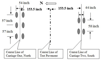
CC1 Pavement Gear Configuration (Click to Zoom)
Pre Trafficking
Prior to full scale trafficking on CC1, slow rolling tests were performed during August to September 1999. In these tests, the testing vehicle was rolled at a speed of 0.5 ft./sec (0.15 m/sec) with 12,000 lbs. (53.4 kN) and 24,000 lbs. (106.8 kN) wheel loads for rigid pavements and 24,000 lbs. (106.8 kN), 30,000 lbs. (133.5 kN) and 36,000 lbs. (160.1 kN) wheel loads for flexible pavements.
Loads were selected such to minimize pavement damage. To investigate the degree of load interaction an analysis of slow rolling test data for different load levels, gear configuration and transverse offsets was performed.
To evaluate the effect of interaction between landing gears on pavement response, gear separation tests were performed as a part of the slow rolling tests. The effect of spacing between two 4-wheel gears, 4-wheel and 6-wheel gear, and two 6-wheel gears were evaluated.
A total of 822 response tests were conducted for the flexible test items with 137 tests for each item. A total of 252 response tests were also conducted on the rigid test items with 84 tests for each item.
Full Scale Trafficking
Full scale trafficking of CC1 started after the completion of the response tests in February 2000.
The test item, dates, wheel loads, and loading passing for each stage of trafficking are summarized in the table below. Trafficking was performed at 5 mph (8 km/h). Wheel loads were set at 45,000 lbs. (20.4 tonnes) with a target tire pressure of 188 psi (1296 kPa).
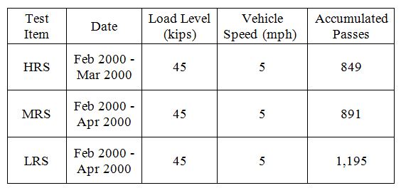
CC1 Rigid Traffic Testing (Click to Zoom)
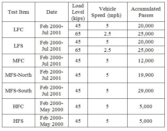
CC1 Flexible Traffic Testing (Click to Zoom)
Wander Pattern
The CC1 Test wander pattern and positions is illustrated in the figure below. To simulate aircraft wander, a wander pattern consisting of a fixed sequence of 66 vehicle passes (33 in east to west and 33 in west to east directions) was used. The 66 passes were arranged in nine equally spaced wander positions at intervals of 10.25-inches (260-mm).
The number of repetitions at each wander position in a complete wander cycle is show below. The wander pattern was intended to approximate a normal distribution of aircraft traffic with a “wander width” of 70-inches; that is the normal distribution that results in 75% of traffic passes concentrated in a 70-inch wide width. It can be shown that the standard deviation of such a distribution is 30.54 inches.
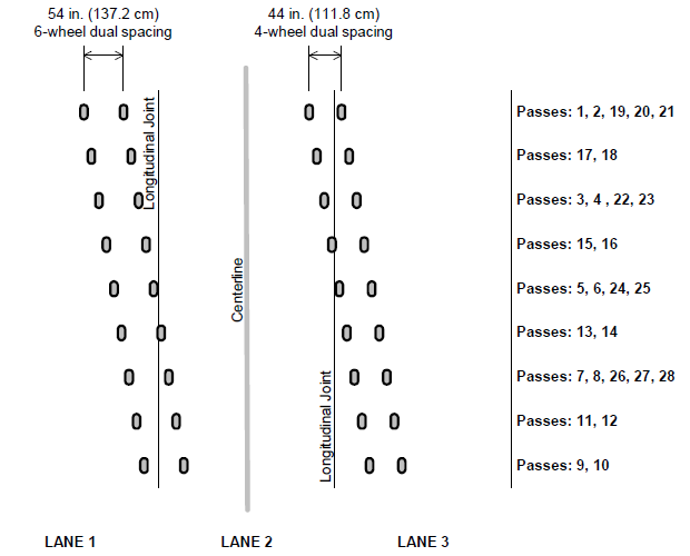
CC1 6-Wheel and 4-Wheel Wander Pattern (Click to Zoom)
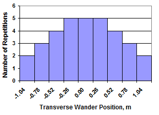
CC1 Wander Distribution (Click to Zoom)
Negative and positive positions of the gear centerlines correspond to the north and south of the pavement centerline, respectively. Travel direction is eastward for odd sequence numbers and westward for even sequence numbers. The transverse position of the gears was changed only at the start of the eastward repetitions. That is, westward repetitions always had the wheels following in the same paths as in the preceding eastward repetition.
To minimize the interaction of gear loads at the subgrade level for the flexible pavement, the south and north carriages maintained an equal lateral distance at each step of the wander pattern. Since the traffic testing of rigid and flexible pavements was performed at the same time, this was applied for the rigid pavement as well.
To download the complete wander table used for the CC1 Traffic Test click here.
Pavement Monitoring
During the full scale trafficking of CC1 in pavement sensors (MDDs) were monitored for permanent deformation of layers. HWD tests were conducted at various stages of trafficking to track the structural deterioration of the pavement sections. In addition, rut depth monitoring was performed using several transverse surface profile (TSP) measuring devices including the rolling inclinometer and straightedge.
Return to Construction Cycle 1 Overview