Instrumentation Plan
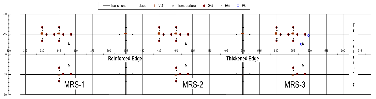
Sensor Diagram
A total of 274 sensors were installed in the test pavement, which included 26 vertical displacement transducers (VDs) and 174 embedded strain gages (EGs) in the concrete layer. The other 74 sensors were 36 surface strain gages and 2 pressure cells on upper surface of concrete layer, as well as 36 thermistors distributed along the depths of concrete layer and base layer.
Click here to download the CC6 Sensor Diagram pdf file.
Sensor Table
Click here to download CC6 Sensor Micro Excel File.
Note that sensor locations are defined by an x, y, z position. In this system, x is the longitudinal position (station) in feet referenced to a point along the facility centerline, and y is the transverse position (offset) in feet north (negative value) or south (positive value) of the centerline. The third coordinate z represents depth in inches below the finished surface of the test item. Note: This file does not include the 36 surface strain gages or 36 thermistors.