NDT Plan & Data
CC6 NDT Test Plan after Construction
Free-Free Resonance Column (FFRC)
Every specimen sampled during the slab construction will be tested prior any destructive testing.
Portable Seismic Pavement Analyzer (PSPA)
After the slabs have completed the curing period a PSPA base line will be taken at 28 days after placement. Every single of the 60 slabs will be tested at the center of the slab. After the baseline testing, the slabs will be tested every 1,000 passes.
GPR Measurements
Measurements will be taken longitudinally at 3 different locations (center lane & 15 ft. north & 15 ft south of the center lane) along the 300 ft (3 different test sections).
Five different walking speed levels will be used. The acquired data will be compared. Two different types of antenna (900 MHz & 500 MHz) will be compared. Higher frequency provides higher resolution but lower penetrating depth.
Using the GPR try to locate dowel bars, identifying them before concrete placement using surveying equipment if possible.
MIT
If purchased the MIT equipment for dowel misalignment can be used to detect the dowels position and compare dowels location with those identify by GPR.
Profiling Device
At least 3 different transverse locations per test item will be tested. Baseline after 28 days from placement and before any load is applied. There after every 1,000 passes.
HWD TEST PLAN FOR CC6
Draft 08/20/2009
OBJECTIVES
-
Pavement homogeneity.
- Backcalculation of pavement material properties;
- Verification of sensor’s workability;
- Correlation of responses under HWD and wheel load.
- Check joint load transfer capabilities.
BACKCALCULATION OF PAVEMENT MATERIAL PROPERTIES
-
When: After the slabs aged more than 28 days
- Where: Center of each slab
- Plate Size: 2 inches
- Procedures: Three drops, 12,000, 24,000 and 36,000 lbs at each location
- Who: Matt Willson
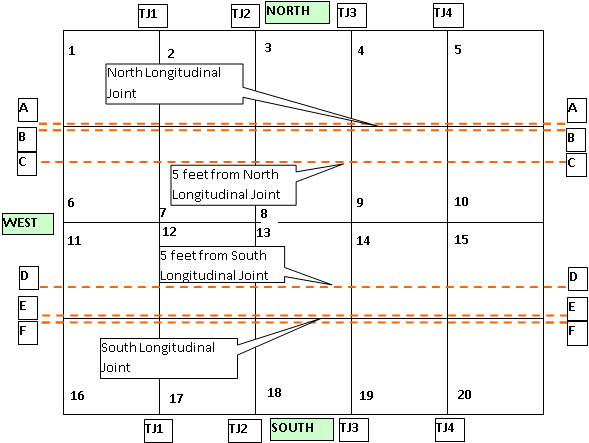
Figure 1 Slabs number in test section.
SENSOR WORKABILITY VERIFICATION & JOINT LOAD TRANSFER CAPABILITY MEASUREMENT
- When: April 12 to 14, 2004.
- Where: FWD vehicle may follow lines AA, BB, CC, DD, EE and FF in Figure 1, in any direction to conduct the tests. The detailed loading locations are:
- Along AA and BB, the middle of longitudinal joints between S3 & S8, and S4 & S9.
- Along EE and FF, the middle of longitudinal joints between S13 & S18, and S14 & S19.
- Along CC and DD lines, drop load at both sides of all four transverse joints. Examples: Along line CC, on the S6 and S7 sides between S6 and S7, on the S7 and S8 sides between S7 and S8, etc.
- Following slab center also need to be tested for checking the sensors: S8 (north side of the pavement), and S14 (south side of the pavement).
- Plate Size: 12 inches
- Procedures: Three drops, 12,000, 24,000 and 36,000 lbs at each location
- Hint: SPU must be turned on and off before and after each FWD loading. The frequency should be set as high as possible (no lower than 100 points/second)
- Who: Five people are needed to conduct the tests. Matt Willson (HWD), Frank Pecht (SPU), xxx (Monitoring), xxx (Guiding location and making notes) and xxx (Checking the data).
NDT Plan and Data Zip file