CC8 Nondestructive Testing
Nondestructive testing (NDT) is the examination of a material to determine its properties, serviceability, and condition without removing or damaging the material. This saves time and money compared to traditional destructive methods such as coring and excavation. In addition, NDT does not require any installation to be done during construction, which allows testing to be performed at any surface location. For NAPTF Construction Cycles (CCs), NDT is used to evaluate and monitor structural and functional changes in the pavement due to traffic loads. NDT data is a valuable resource for the research team at the NAPTF, playing an important role in defining the pavement’s response to loading and performance, and providing insight into parts of the pavement that cannot be seen.
CC8 NDT Summary
For CC8, fourteen NDT devices and methods were used throughout the four test phases to study the effects of traffic loads on the pavement structures. For each phase, tests were performed prior to trafficking to establish baseline data, during trafficking to monitor the changes in the pavement condition, and following trafficking to evaluate the effects of traffic loads. The test phases each required a unique selection of NDT methods to accomplish their individual research objectives and are detailed in the Comprehensive NDT Test Plans linked below.
CC8 Phase 1 Overload NDT Test Plan
CC8 Phase 2 Overlay NDT Test Plan
CC8 Phase 3 Joint Comparison NDT Test Plan
CC8 Phase 4 Strength & Fatigue NDT Test Plan
NDT Devices and Methods
Different NDT devices and methods evaluate different structural and functional characteristics of the test pavement. While some methods were used individually to provide unique information, some were used in conjunction with others for complementary and comparative studies. The devices and methods used for CC8 included:
- Heavy Weight Deflectometer (HWD)
- Portable Seismic Property Analyzer (PSPA)
- Inertial Profiler
- SurPro 2000 Profiler
- Dipstick Profiler
- Straightedge
- Rail-to-Rail Profiler
- Truss Profiler
- Joint Groove Profiler
- 2D and 3D Imaging
- Ground Penetrating Radar (GPR)
- ELAtextur
- MIT Scanner BT
- Visual pavement survey
While each method is briefly described below, more detailed information is available at the FAA Nondestructive Testing webpage.
NDT Devices
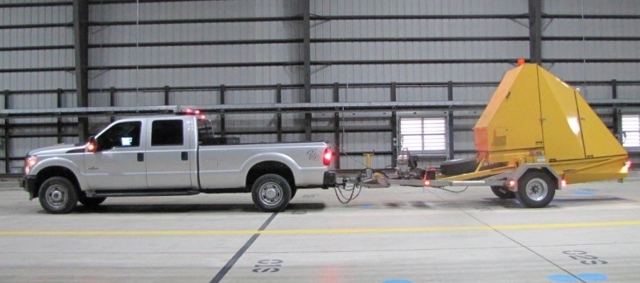
KUAB HWD (click to Zoom)
The Heavy Weight Deflectometer (HWD) is operated by dropping a known weight onto pavement and measuring its deflection response. Through analysis, the strength of each pavement layer is estimated. More information can be found on the HWD page. HWD testing was performed weekly on select phases of CC8.
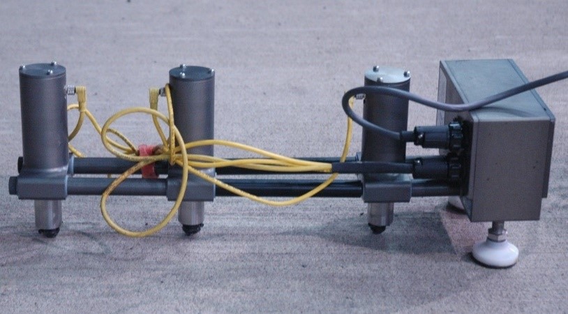
PSPA (Click to Zoom)
The Portable Seismic Property Analyzer (PSPA) is a device that generates and monitors seismic waves in the pavement. Analysis can determine layer strength, similar to the HWD's results. More information can be found on the PSPA page. PSPA testing was performed weekly on select phases of CC8.
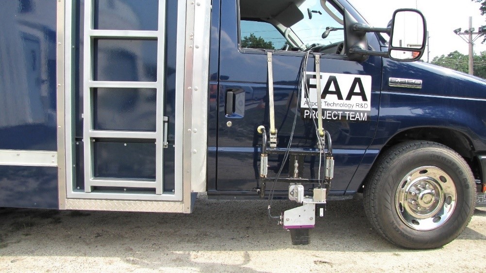
Inertial Profiler (click to Zoom)
The Inertial Profiler is a vehicle-mounted system that uses multiple instruments to record surface profiles at high speeds. A profile can be used to quantify surface roughness and smoothness through software simulation. More information can be found on the inertial profiler page and ProFAA page.
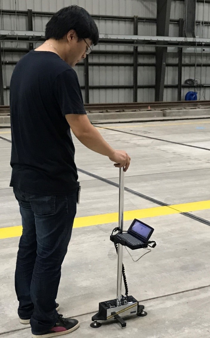
SurPro 2000 (click to Zoom)
The SurPro 2000 is a walk-behind surface profiler owned by the FAA. As its classification suggests, the profiler is pushed by an operator as it records a surface profile, which is comparable to those from other profilers. On CC8, it was used to determine roughness/ smoothness as well as to detect slab curling. More information can be found on the walk-behind surface profiler page.
Dipstick (click to Zoom)
The Dipstick is a walking road profiler that uses an inclinometer to record surface elevation as an operator “walks” the device down the path. Like the SurPro, it was also used to determine roughness/ smoothness and slab curling. More information can be found on the walking road profiler page.
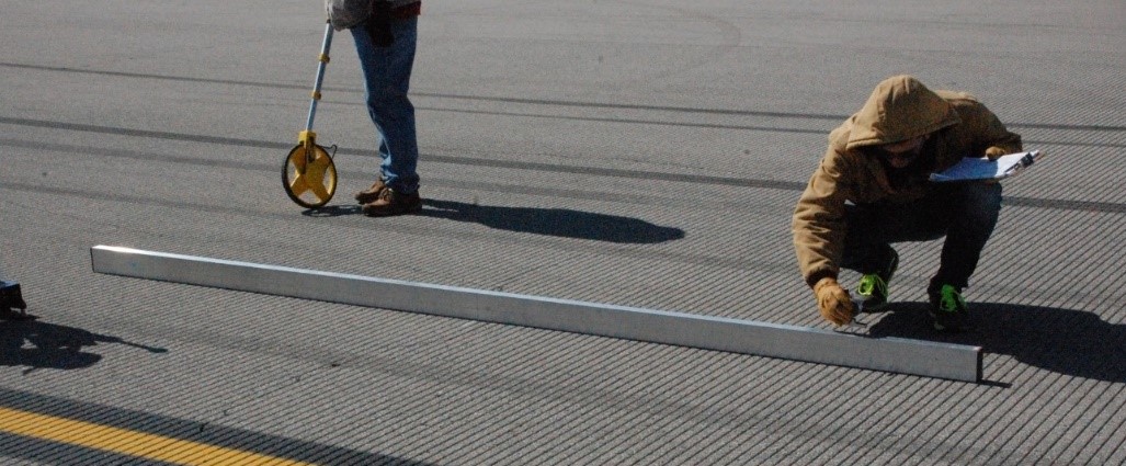
Straightedge (click to Zoom)
The 12-foot Straightedge is used as a reference line for measuring deviation of the pavement surface from grade. Typically used for smoothness acceptance, it was used on CC8 to determine slab movement. More information can be found on the straightedge page.
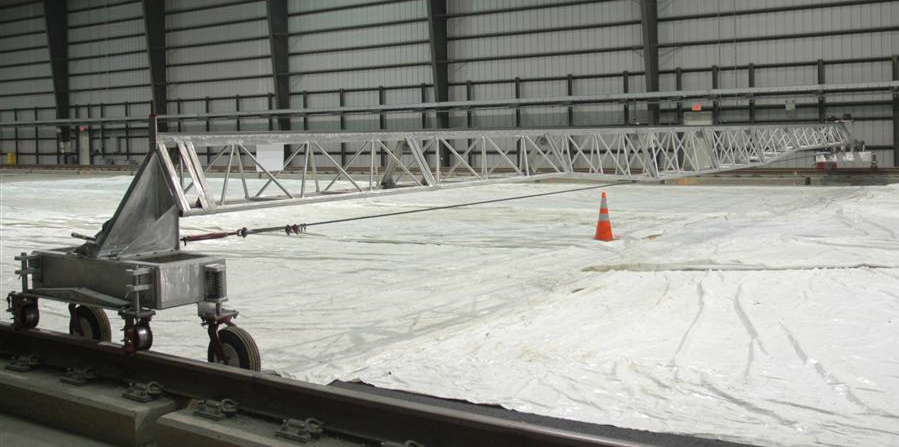
Rail-to-Rail Profiler (click to Zoom)
The Rail-to-Rail Profiler (RTRP) is a large rail-mounted truss that spans the NAPTF with attached distance measuring laser equipment. The laser is able to record a transverse surface profile across the entire pavement section. It was used for roughness/ smoothness testing, slab curling, and distress monitoring on CC8.
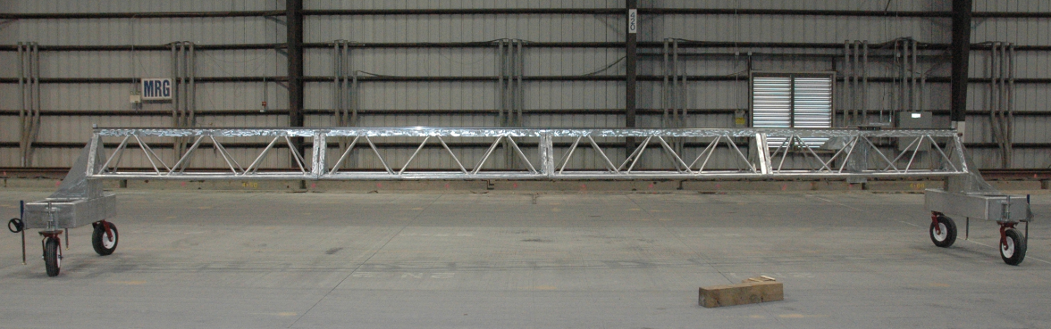
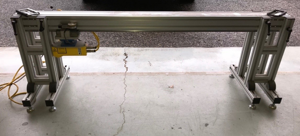
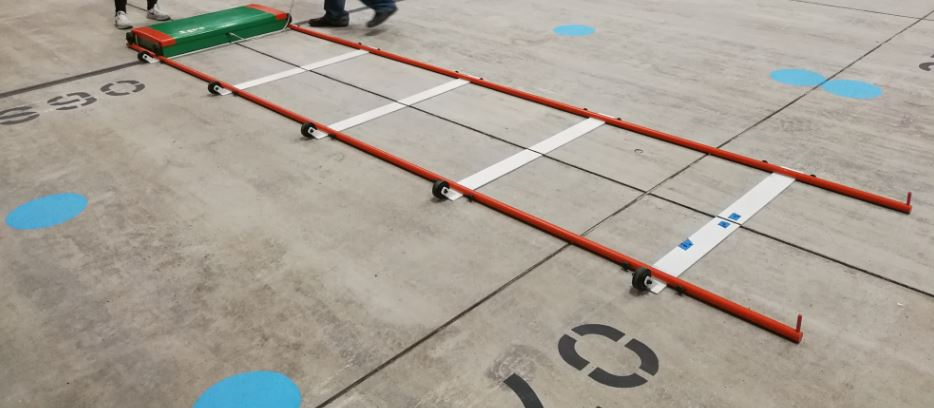
Truss Profiler (click to Zoom)
The Truss Profiler is similar to the Rail-to-Rail Profiler, with the exceptions of it being smaller, covering only part of the section, and is supported on casters instead of rails. The smaller size made it optimal for monitoring joint curling and joint performance on CC8.
Joint Groove Profiler (click to Zoom)
The Joint Groove Profiler is a beam-type transportable profiler that measures the geometry of grooves in the pavement under it across a small section. This was done to measure joint deterioration over time at select locations.
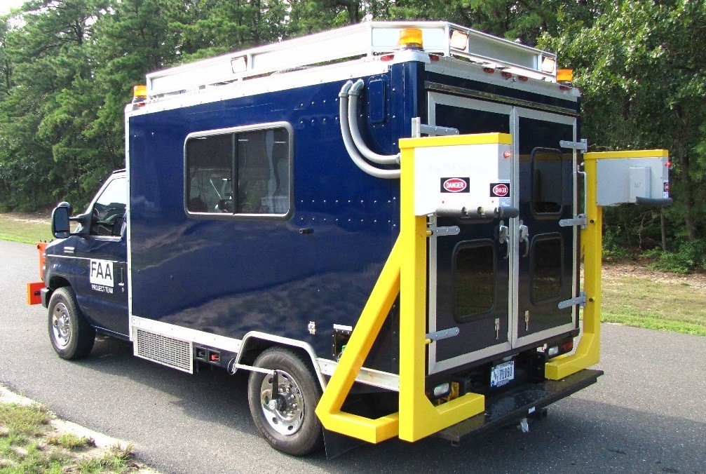
Waylink 2D and 3D Imaging (click to Zoom)
The Waylink 2D and 3D Imaging system makes use of vehicle-mounted lasers that scan the pavement’s surface in wide strips. Through data merging and analysis, pavement distresses can be detected and viewed in software. More information can be found on the 2D/3D mapping page.
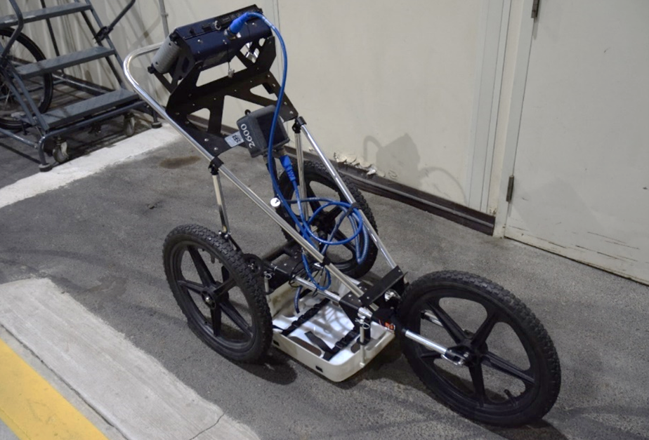
Walk Behind GPR Cart (Click to Zoom)
Ground Penetrating Radar (GPR) uses antennas that direct electromagnetic waves into the structure and receivers that record the reflected signals. Various antennas can be mounted on a vehicle or on a push cart, as shown. On CC8, a cart-type GPR device was used to investigate layer thickness, thickness change, and the pavement support structure. More information can be found on the GPR page.
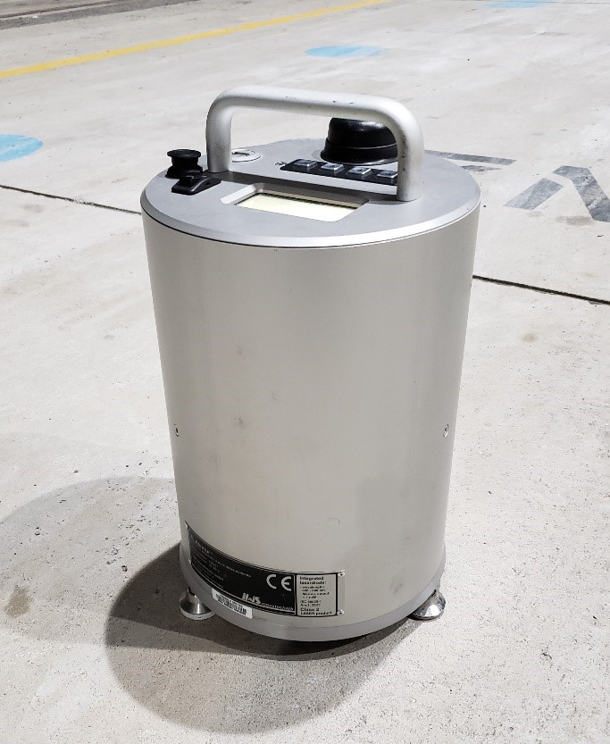
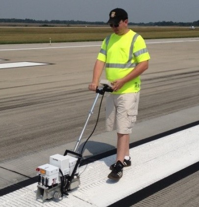
ELAtextur (Click to Zoom)
The ELAtextur, otherwise known as a macro texture laser scanner, is a compact, hand-transportable device that scans the pavement surface underneath it. This scan enables measurement of pavement texture, and was used on CC8 to monitor abrasion. More information can be found on the macrotexture laser scanner page.
MIT Scanner BT (Click to Zoom)
The MIT Scanner BT is a transportable rail-based device that uses the eddy current magnetic principle to detect conductive materials. On CC8, these would be the dowel bars present at some slab joints. The MIT Scanner was used to verify the dowel bar placement after construction and after trafficking.
Pavement Visual Survey
A pavement visual survey is a meticulous examination of the entire pavement surface to identify distresses caused by traffic loading. It requires no equipment other than flashlights, chalk, and other basic hand tools to aid in locating and measuring very fine cracks. For CC8, a survey was performed each day after trafficking to document longitudinal and transverse cracking, diagonal cracking, corner breaks, intersecting cracking, shattered slabs, and shrinkage cracking. Following the survey, the Structural Condition Index (SCI) was calculated to quantify the level of damage to the pavement
NDT Plan During Each Phase
Not all equipment was used on each phase of CC8, with time being spent to collect only data that would fulfill each phase’s objectives. The following chart indicates the devices and methods used on each phase of CC8.
|
Equipment
|
Phase 1
Overload
|
Phase 2
Overlay
|
Phase 3
Joint Comparison
|
Phase 4
Strength & Fatigue
|
|
HWD
|
X
|
X
|
X
|
X
|
|
LWD
|
|
X*
|
|
|
|
PSPA
|
X
|
X
|
X
|
X
|
|
Inertial Profiler
|
X
|
|
|
|
|
SurPro Profiler
|
X
|
X
|
X
|
X**
|
|
Dipstick Profiler
|
|
X
|
X
|
|
|
Truss Profiler
|
|
X
|
|
|
|
Rail-to-Rail Profiler
|
|
X
|
X
|
|
|
Joint Groove Profiler
|
X
|
|
X
|
|
|
Straightedge
|
|
X
|
|
|
|
2D/3D Imaging
|
X
|
|
X
|
X
|
|
Leica 3D Scan
|
|
|
X**
|
X**
|
|
GPR Cart
|
X
|
|
X
|
X
|
|
ELAtextur
|
X
|
X
|
X
|
|
|
MIT Scanner BT
|
X**
|
X
|
X
|
|
|
Visual Survey
|
X
|
X
|
X
|
X
|
* Although included in the Phase 2 NDT plan, LWD data was only collected during construction.
** Although included in the NDT plan, no data was collected with this device for this phase.
Testing Schedule
For each phase of CC8, tests were performed prior to, during, and following trafficking. The pre-traffic testing established the baseline data while post-traffic testing evaluated the effects of the traffic loads. Tests conducted during trafficking were used to monitor the development of damage and were performed daily and weekly, depending on the method employed. Additionally, Phases 2 and 3 paused trafficking midway through the experiment to perform the entire suite of NDT surveys. The CC8 testing schedule can be summarized as follows:
- Phase 1 Overload:
- Pre-trafficking: February 2016
- Post-trafficking: March 2016, September 2016
- Phase 2 Overlay:
- Pre-trafficking: September 2017
- Post ramp-up: October 2017
- Midway: November 2017
- Post-trafficking: February 2018
- Phase 3: Joint Comparison
- Pre-trafficking: February 2018
- Midway: March 2018, April 2018
- Post-trafficking: November 2018
- Phase 4: Strength and Fatigue
- Pre-trafficking: August 2018
- Post-trafficking: coming soon, testing is ongoing
NDT Results
NDT test data for CC8 is available for download by following the link's below.
Phase 1 Overload Data
Phase 2 Overlay Data
Phase 3 Joint Comparison Data
Phase 4 Strength & Fatigue Data
From the daily pavement surveys, cumulative plots of crack mapping were prepared. On these plots, the distresses were color-coded to separate dates/passes on which the new distresses were observed. The observed cracks were then processed and analyzed as follows: linear cracks for each test item were measured and cumulatively added; and fatigue areas for each test item were measured and cumulatively added.
CC8 Phase 1 Overload Pavement Distress Map and Log
CC8 Phase 2 Overlay Pavement Distress Map and Log
CC8 Phase 3 Joint Comparison Pavement Distress Map and Log
CC8 Phase 4 Strength & Fatigue Pavement Distress Map and Log (Coming Soon)
Return to Construction Cycle 8 Overview