CC8 Pavement Construction/Cross-Section
To meet the test objectives, the FAA project team drafted a conceptual design for three rigid test areas to be constructed within CC8. Each test area was designed to meet the selected testing objectives. The three test areas include:
- Phase 1 Overload and Phase 2 Overlay Test Area
- Phase 3 Joint Comparison Test Area
- Phase 4 Strength & Fatigue Test Area
CC8 was designed in such a way that by varying individual layer thicknesses, the above three test areas would have the same design life (year/failure passes). It should be noted that for the original design, only medium strength subgrade (CBR = 7-8) was considered. FAARFIELD v. 1.305 was utilized with the following assumptions:
- NAPTV configuration – 2D (4-wheel) and 55,000 lbs. per wheel
- Design Flexural Strength – 650 and 900 psi
- Layer Moduli – P-501MR = 4,000,000 psi; P-306MR = 700,000 psi; P-154M = 19,500 psi
Within these test areas, contraction and construction joints were used. Contraction joints were used to control cracking of the pavement due to moisture loss or temperature drops. Construction joints were utilized due to the concrete placement sequence. The five types of joints utilized on the project were as follows: contraction joint (Type C Doweled), contraction joint (Type D Dummy), construction joint (Type E Doweled), construction joint (Type F Butt), and construction joint (sinusoidal keyway).
An overview of the CC8 Plan and Profile View can be seen below. For a pdf version of the CC8 As-Built Drawings click here.
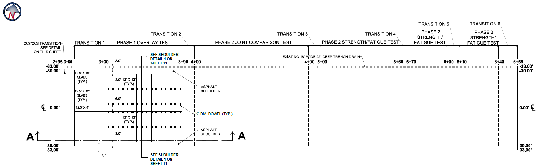
CC8 Plan View (Click to Zoom)
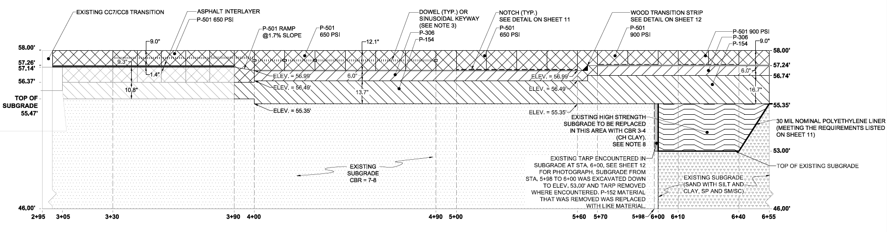
CC8 Profile View (Click to Zoom)
For more information on the Pavement Construction & Cross Section for each experiment click on the links in the table below.
CC8 Phase 1 Overload Test Section
Construction for the Phase 1 Overload Test section included demolition of the existing CC6 PCC pavement structure, conditioning of the in-situ P-152M subgrade to a target CBR = 7-8, placement of two lifts of P-154M subbase, and placement of one lift of P-501MR PCC surface course.
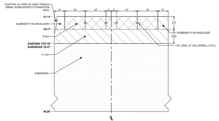
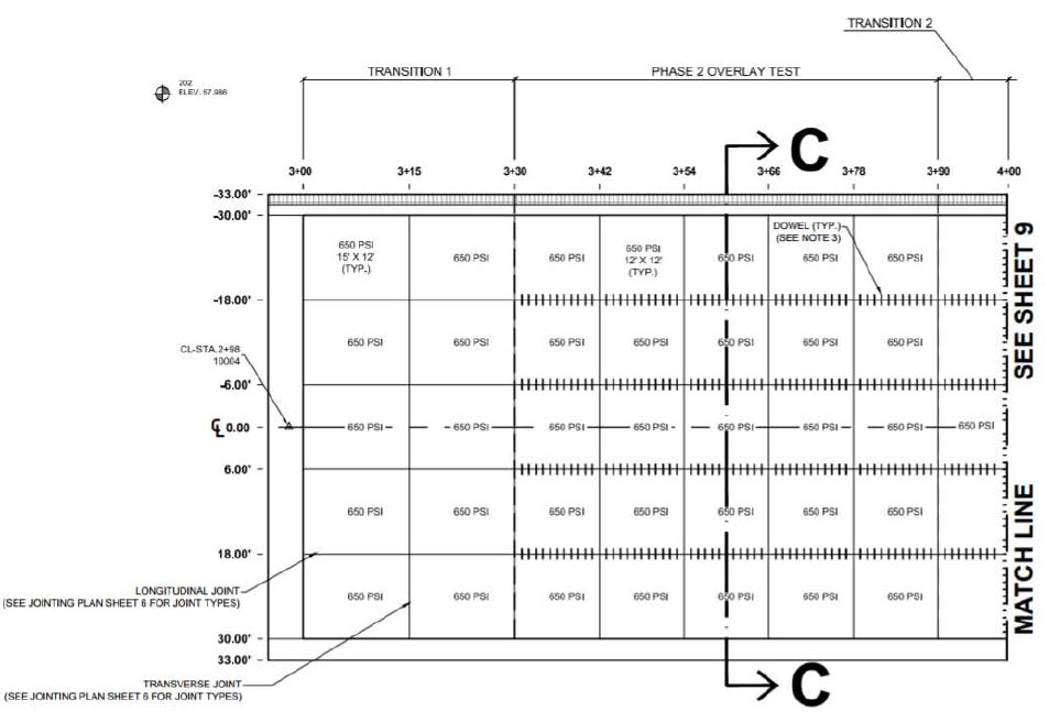
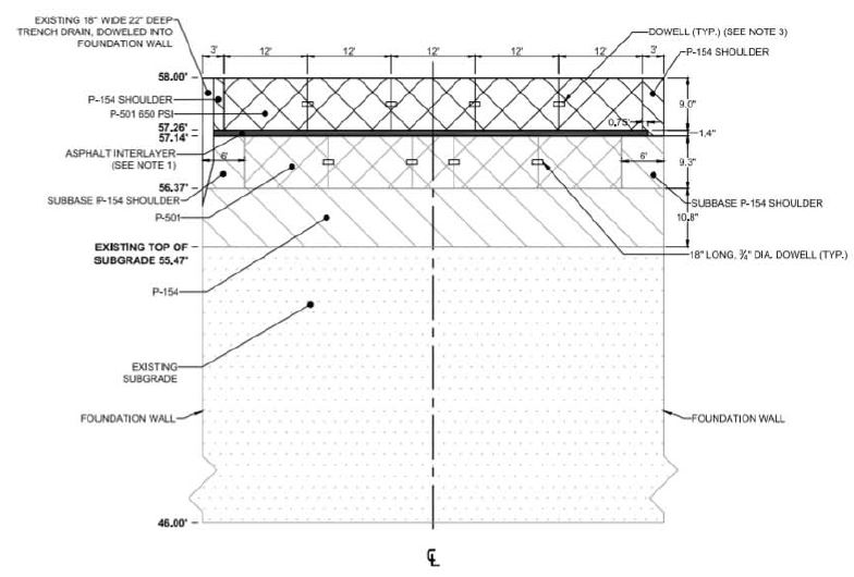
The design thicknesses for the Overload Test section were as follows: P-154M = 10 in. and P-501MR = 9 in. The Overload test area was constructed between STA 3+30 and 3+90 and was between Transition 1 (STA 3+00 to 3+30) and Transition 2 (STA 3+90 to 4+00). Transitions were utilized as a way to distinguish test items as well as to allow time for the NAPTV to get up to speed and for the load to stabilize.
The width of the section ran from -33 ft. (north side) to +33 ft. (south side), which included 6 ft. of existing subbase shoulders on both sides. For the P-501MR layer, longitudinal joints were placed such that the pattern across the remaining 54 ft. width produced ten 12 ft. by 12 ft. slabs each on the north and south sides of the test area, with the middle 6 ft. slabs being utilized as transitions.
The transverse joints of the test area slabs were contraction joint Type D Dummy, and all longitudinal joints were construction joint Type E Doweled using 3/4 in. diameter dowels. Compression seals were utilized for all joints.
The figures below shows the as-built plan and profile drawings for the Overload test design (Note: due to construction variance, as-built elevations may differ from the design).
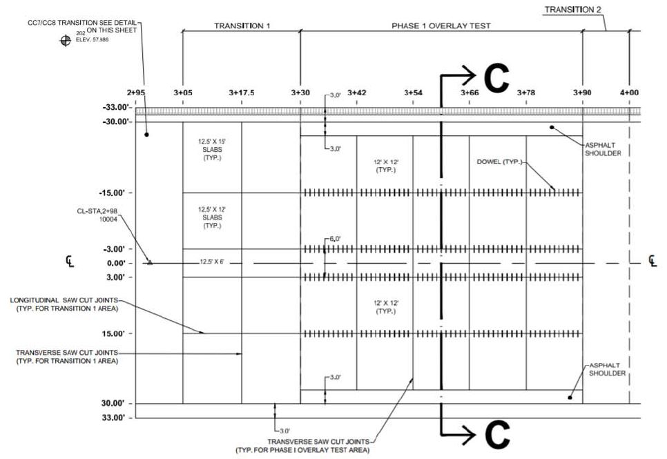
CC8 Phase 1 Overload Plan View (Click to Zoom)
CC8 Phase 1 Overload Profile View (Click to Zoom)
CC8 Phase 2 Overlay Test Section
The Overlay Test section included placement of the P-404MR bituminous bondbreaker layer and one lift of the P-501MR PCC surface course on top of the already constructed and tested Overload test design.
The design thicknesses for the Overlay Test section were P-404MR = 1 in. and P-501MR = 9 in. The stationing and transition locations for the Overlay Test area were the same as those described for the Phase 1 Overload Test Section.
The width of the section ran from -33 ft. (north side) to +33 ft. (south side). However, the section included only 3 ft. of subbase shoulders on both sides where the Overload section included 6 ft. on each side. For the P-501MR layer, five lanes were poured along the 60 ft. width, resulting in longitudinal joints being offset 3 ft. from the longitudinal joints on the Overload Test area.
Transverse joints were cut such that twenty-five 12 ft. by 12 ft. slabs were formed in the test area. The transverse joints of the test area slabs were contraction joint Type D Dummy, and all longitudinal joints were construction joint Type E Doweled using 3/4 in. diameter dowels. Compression seals were utilized for all joints.
The figures below shows the as-built plan and profile drawings for the Overlay test design (Note: due to construction variance, as-built elevations may differ from the design).
CC8 Phase 2 Overlay Plan View (Click to Zoom)
CC8 Phase 2 Overlay Profile View (Click to Zoom)
CC8 Phase 3 Joint Comparison Test Section
Construction of the Joint Comparison Test section included the conditioning of the in-situ P-152M subgrade to a target CBR = 7-8, placement of two lifts of P-154M subbase, placement of one lift of P-306MR lean concrete base course, and placement of one lift of P-501MR PCC surface course.
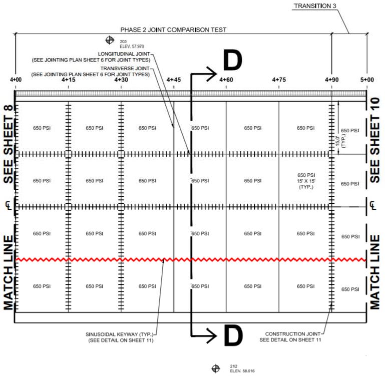
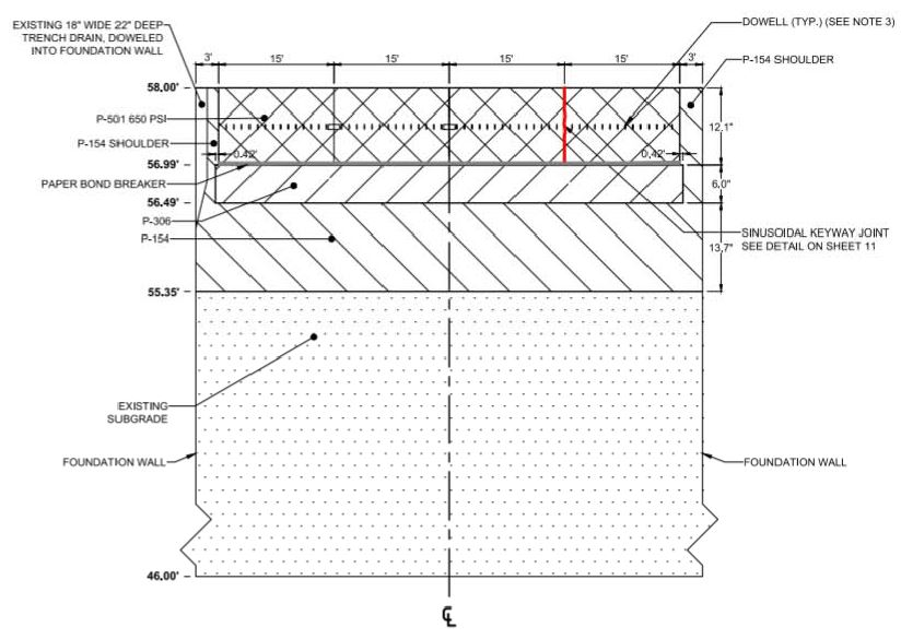
The design thicknesses for the Overload section were P-154M = 13 in., P-306MR = 6 in., and P 501MR = 12 in. The Joint Comparison Test design was constructed between STA 4+00 and 4+90 and was flanked between Transition 2 (STA 3+90 to 4+00) and Transition 3 (STA 4+90 to 5+00).
The width of the section ran from -30 ft. (north side) to +30 ft. (south side), with an additional 3 ft. of P-154M subbase on each side for shoulders. For the P-501MR layer, a total of twenty-four 15 ft. by 15 ft. slabs were constructed in the test area.
Longitudinal joints were construction joint Type E Doweled using 1 in. diameter dowels at an offset of -15 ft. (north side) and along the centerline. Longitudinal joints at an offset of +15 ft. (south side) were constructed using a construction sinusoidal keyway joint.
Transverse joints were constructed with contraction joint Type C Doweled using 1 in. diameter dowels at STA 4+00, 4+15, 4+30, and 4+90 and contraction joint Type D Dummy otherwise. Compression seals were utilized for all joints. The figures below shows the as-built plan and profile drawings for the Joint Comparison test design (Note: due to construction variance, as-built elevations may differ from the design).
CC8 Phase 3 Joint Comparison Plan View (Click to Zoom)
CC8 Phase 3 Joint Comparison Profile View Section D (Click to Zoom)
CC8 Phase 4 Strength & Fatigue Test Section
Construction of the Strength & Fatigue Test Section included conditioning of the in-situ P-152M subgrade (STA 5+00 to STA 6+00) to a target CBR = 7-8, placement of three lifts of P-152M subgrade (STA 6+00 to 6+40) to a target CBR = 3-4, placement of two lifts of P-154M subbase, placement of one lift of P-306MR lean concrete base course, and placement of one lift of P501MR PCC surface course.
The design thicknesses for the Strength & Fatigue section (STA 5+00 to 6+00) were P-154M = 13 in., P-306MR = 6 in., and P-501MR = 12 in. The design thicknesses for the Strength & Fatigue section (STA 6+00 to 6+55) were P-154M = 16 in., P-306MR = 6 in., and P-501MR = 9 in. The Strength & Fatigue Test design has three different test items:
- Medium strength subgrade (CBR = 7-8) with 650 flexural strength P-501MR (STA 5+00 to 5+60)
- Medium strength subgrade (CBR = 7-8) with 900 flexural strength P-501MR (STA 5+70 to 6+00)
- Low strength subgrade (CBR = 3-4) with 900 flexural strength P-501MR (STA 6+10 to 6+40)
Transition 4 (STA 5+60 to 5+70), Transition 5 (STA 6+00 to 6+10), and Transition 6 (STA 6+40 to 6+55) were located within the Strength & Fatigue test area.
The width of the section ran from -30 ft. (north side) to +30 ft. (south side), with an additional 3 ft. of P-154M subbase on each side for shoulders. For the first test area (STA 5+00 to 5+60), a total of sixteen 15 ft. by 15 ft. slabs were constructed. For the second and third test areas (STA 5+70 to 6+00 and STA 6+10 to 6+40), a total of eight 15 ft. by 15 ft. slabs were constructed for each section. A triangular wood chamfer ran longitudinally along the test areas at an offset of +10 ft. (south side) to guarantee bottom-up cracking.
All transverse and longitudinal joints were constructed using construction Type F Butt Joints and compression seals. The figures below shows the as-built plan and profile drawings for the Strength and Fatigue test design (Note: due to construction variance, as-built elevations may differ from the design).
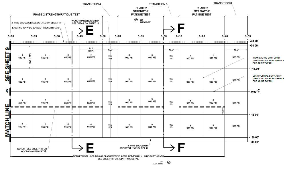
CC8 Phase 4 Strength & Fatigue Plan View (Click to Zoom)
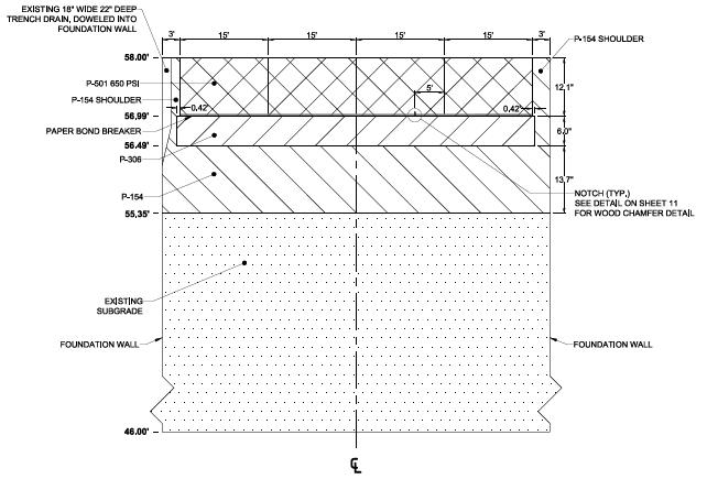
CC8 Phase 4 Strength & Fatigue Profile View Section E (Click to Zoom)
.jpg?ver=2018-08-15-093501-440)
CC8 Phase 4 Strength & Fatigue Profile View Section F (Click to Zoom)
Return to Construction Cycle 8 Overview