CC8 Phase 3 Joint Comparison Traffic Test
The National Airport Pavement Test Vehicle (NAPTV) in the NAPTF is a rail-based test vehicle capable of simulating an aircraft weighing up to 1.3 million pounds. The NAPTV consists of two carriages, a north carriage and a south carriage, each that can accommodate up to five load modules. Each load module can support two wheels, allowing for configurations of up to 20 wheels. The NAPTV can apply loads of up to 75,000 pounds per wheel and simulates aircraft wander by varying the lateral position of the carriages.
For more information on the Phase 3 Joint Comparison Traffic Test click on the links in the table below.
To be directed to the CC8 Phase 3 Joint Comparison Comprehensive Test Plan, click here.
Gear Configuration
For the Phase 3 Joint Comparison Test a two wheel gear (D) was used on the north and south carriages for the initial full-scale traffic test. The dimensions of the load configuration are illustrated in the figure below.
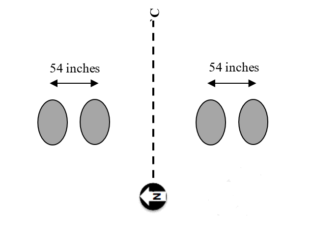
CC8 Phase 3 Joint comparison Gear Configuration (Click to Zoom)
Pre Trafficking
Prior to full scale trafficking on the Phase 3 Joint Comparison section the test pavement was trafficked using a two-wheel (D) gear at a load of 10,000 pounds per wheel. The seating load pattern consisted of 21 tracks spaced every 10 inches to cover the pavement width (except for areas near the north and south shoulders that are out of range of the gear). Slab vertical movements during seating were monitored using ECS deflection sensors.
Following the seating load wander, HWD tests were performed at the locations specified. The HWD testing was conducted with a four-drop loading sequence beginning with an approximate 36,000-pound seating load. The subsequent loads were approximately 12,000 pounds, 24,000 pounds, and 36,000 pounds. All PSPA measurements were collected from slab centers and ECS installed corners. The baseline HWD and PSPA measurements were used to back calculate layer moduli, and to monitor slab curling and changes of support conditions. All subsequent tests were referenced to the baseline to monitor slab curling and changes in support conditions.
A ramp-up response test was conducted with a full wander pattern. The purpose of this test was to make sure all systems were operating properly, and to assist in making the final decision about the wheel load to be used for the traffic test. A two-wheel (D) gear was used for both the north and south side. A four step process was used to achieve the maximum strain response:
- A full traffic wander (66 passes) was applied on both north and south at the initial wheel load of 50,000 pounds. The condition of slabs was monitored to verify that the pavement was not damaged. Baseline sensor readings were recorded for dynamic sensors.
- Critical tracks of maximum strain gage responses were verified. The maximum strain on the critical track for all EGs was identified.
- The maximum strain responses at slab top and bottom in step 2 were extrapolated to the extreme fiber. The extrapolated strains were compared to the FAARFIELD calculations.
- The wheel load was increased in increments of 2,500 pounds. Only the critical tracks were trafficked for both directions (W→E and E→W). Step 3 was repeated until either the peak slab top or bottom tensile strain was 90% of the FAARFIELD prediction.
Full Scale Trafficking
Full scale trafficking of Phase 3 Joint Comparison was conducted on both the north and south side using the D gear configuration. The initial plan considered continuing traffic until a single digit SCI condition is achieved on both sides. If a single digit SCI was attained on either side of the pavement, traffic would stop on that side, but continue on the other side until the SCI was less than 10. However, it was later determined that termination of traffic had to be decided based on load transfer efficiency parameters rather than SCI only.
Full-scale traffic test was conducted in two stages. In both stages, a ramp-up response test was conducted to identify appropriate load levels and gear configurations. For CC8 Phase 3 Joint Comparison experiment, it was assumed that failure of the test pavement would be attained when the average deflection-based load transfer efficiency of either contraction (transverse) or construction (longitudinal) is at 60% or below. Failure in terms of load transfer efficiency of joints was anticipated to occur after attaining the design failure condition of SCI=80.
|
Day No
|
Date
|
Number of Passes
|
Number of
Wanders Completed
|
Cumulative Passes
North and South
|
|
1
|
3/1/18
|
396
|
6
|
396
|
|
2
|
3/2/18
|
594
|
9
|
990
|
|
3
|
3/5/18
|
594
|
9
|
1584
|
|
4
|
3/6/18
|
594
|
9
|
2178
|
|
5
|
3/7/18
|
528
|
8
|
2706
|
|
6
|
3/8/18
|
594
|
9
|
3300
|
|
7
|
3/12/18
|
594
|
9
|
3894
|
|
8
|
3/13/18
|
594
|
9
|
4488
|
|
9
|
3/14/18
|
594
|
9
|
5082
|
|
10
|
3/15/18
|
594
|
9
|
5676
|
|
11
|
3/19/18
|
594
|
9
|
6270
|
|
12
|
3/20/18
|
594
|
9
|
6864
|
|
13
|
3/22/18
|
396
|
6
|
7260
|
|
14
|
3/26/18
|
594
|
9
|
7854
|
|
15
|
3/27/18
|
594
|
9
|
8448
|
|
16
|
3/28/18
|
594
|
9
|
9042
|
|
17
|
3/29/18
|
594
|
9
|
9636
|
|
18
|
4/02/18
|
528
|
8
|
10164
|
|
19
|
4/03/18
|
594
|
9
|
10758
|
|
20
|
4/04/18
|
594
|
9
|
11352
|
|
21
|
4/05/18
|
594
|
9
|
11946
|
|
22
|
4/09/18
|
594
|
9
|
12540
|
|
23
|
4/10/18
|
594
|
9
|
13134
|
|
24
|
4/16/18
|
0
|
0
|
13134
|
|
25
|
4/17/18
|
0
|
0
|
13134
|
|
26
|
4/19/18
|
594
|
9
|
13728
|
|
27
|
4/23/18
|
594
|
9
|
14322
|
|
28
|
4/24/18
|
594
|
9
|
14916
|
|
29
|
4/25/18
|
594
|
9
|
15510
|
|
30
|
4/26/18
|
594
|
9
|
16104
|
|
31
|
4/30/18
|
594
|
9
|
16698
|
|
32
|
5/1/18
|
594
|
9
|
17292
|
|
33
|
5/2/18
|
594
|
9
|
17886
|
|
34
|
5/3/18
|
462
|
7
|
18348
|
|
35
|
5/7/18
|
594
|
9
|
18942
|
|
36
|
5/8/18
|
594
|
9
|
19536
|
|
37
|
5/9/18
|
594
|
9
|
20130
|
|
38
|
5/14/18
|
594
|
9
|
20724
|
|
39
|
5/16/18
|
594
|
9
|
21318
|
|
40
|
5/17/18
|
594
|
9
|
21912
|
|
41
|
5/21/18
|
594
|
9
|
22506
|
|
42
|
5/22/18
|
594
|
9
|
23100
|
|
43
|
5/23/18
|
594
|
9
|
23694
|
|
44
|
5/24/18
|
594
|
9
|
24288
|
|
45
|
5/29/18
|
594
|
9
|
24882
|
|
46
|
5/30/18
|
594
|
9
|
25476
|
|
47
|
5/31/18
|
594
|
9
|
26070
|
|
48
|
6/4/18
|
594
|
9
|
26664
|
|
49
|
6/5/18
|
594
|
9
|
27258
|
|
50
|
6/6/18
|
594
|
9
|
27852
|
|
51
|
6/7/18
|
594
|
9
|
28446
|
|
52
|
6/11/18
|
594
|
9
|
29040
|
|
53
|
6/12/18
|
594
|
9
|
29634
|
|
54
|
6/13/18
|
594
|
9
|
30228
|
|
55
|
6/14/18
|
594
|
9
|
30822
|
|
56
|
6/18/18
|
594
|
9
|
31416
|
|
57
|
6/19/18
|
594
|
9
|
32010
|
|
58
|
6/20/18
|
594
|
9
|
32604
|
|
59
|
6/21/18
|
528
|
8
|
33132
|
|
60
|
6/25/18
|
594
|
9
|
33726
|
|
61
|
6/26/18
|
594
|
9
|
34320
|
|
62
|
6/27/18
|
594
|
9
|
34914
|
|
63
|
6/28/18
|
594
|
9
|
35508
|
|
64
|
7/2/18
|
458
|
6.9 *
|
35966
|
|
65
|
7/23/18
|
598
|
9.1
|
36564
|
|
66
|
7/24/18
|
594
|
9
|
37158
|
|
67
|
7/25/18
|
594
|
9
|
37752
|
|
68
|
7/26/18
|
594
|
9
|
38346
|
|
69
|
7/30/18
|
594
|
9
|
38940
|
|
70
|
7/31/18
|
594
|
9
|
39534
|
|
71
|
8/1/18
|
594
|
9
|
40128
|
|
72
|
8/2/18
|
594
|
9
|
40722
|
|
73
|
8/6/18
|
594
|
9
|
41316
|
|
74
|
8/7/18
|
594
|
9
|
41910
|
|
75
|
8/8/18
|
594
|
9
|
42504
|
|
76
|
8/9/18
|
198
|
3
|
42702
|
* - vehicle electric problem
Wander Pattern
The wander pattern consisted of 66 passes with each passage of the NAPTV to the east being counted as a pass, and the return to the west counted as a second pass. These 66 passes were arranged in 9 tracks, as shown in the figure below. For Track 0, the outside tire of each dual aligns with the longitudinal joint centered within each test item.
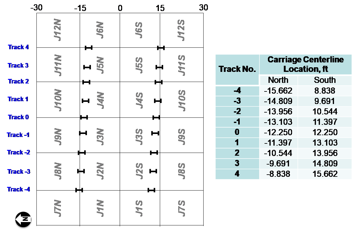
CC8 Phase 3 Joint Comparison Wander Pattern (Click to Zoom)
To download the complete wander table used for the Phase 3 Joint Comparison Traffic Test, click here.
Pavement Monitoring
During the full scale trafficking of the Phase 3 Joint Comparison section static and dynamic responses were monitored for both gauge failure and environmental changes. In addition, the overall pavement condition was monitored using a manual distress survey and SCI calculation. HWD and PSPA testing was also performed on a weekly basis to aid in monitoring the pavement condition.
Return to Construction Cycle 8 Overview