Dynamic Sensor Data
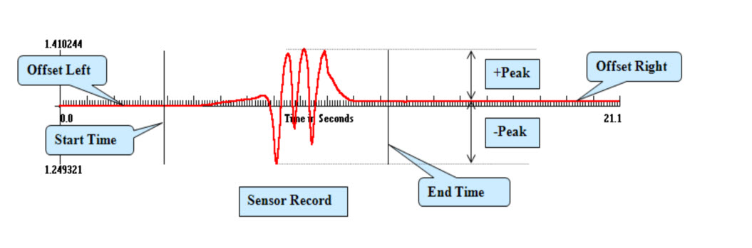
Contains dynamic sensor responses, including peak values and full dynamic records. Fields are defined in the following list. The following figure illustrates properties of the sensor record as given in the Dynamic_data table.
Definition of Fields in Table Dynamic_data
|
TrafficID
|
Unique number assigned to identify each vehicle passing event. The numbers from 1 to 12540 refer to the north side trafficking, and numbers ranging from 12541 to 54012 refer to south side trafficking. North side detail includes 1 to 12540 for LFC1NW, LFC1NE, LFC2NW, LFC2NE, LFC3N, and LFC4N. Further detail of the south side includes 12541 to 32430 for LFC3S and LFC4S; 32431 to 41076 for LFC2SW and LFC2SE; 41077 to 54012 for LFC1SW and LFC1SE.
|
|
SensorID
|
Number assigned to an individual sensor in the "SPU" table.
|
|
EventNo
|
Number assigned to an event in the “Traffic” table. An event is defined as a vehicle movement with loads.
|
|
StartTime
|
Time after the start of an event corresponding to the first data sample added to the SensorRecord (seconds).
|
|
StartVehiclePosition
|
The vehicle position corresponding to time StartTime (feet).
|
|
EndTime
|
Time after the start of an event corresponding to the last data sample added to the SensorRecord (seconds).
|
|
EndVehiclePosition
|
The vehicle position corresponding to time EndTime (feet).
|
|
OffsetLeft
|
Average value of the sensor reading prior to the initial load response (sensor units).
|
|
OffsetRight
|
Average value of the sensor reading following the load response (sensor units).
|
|
FilterFreq
|
Frequency of the applied data filter (Hz).
|
|
Peak1Time
|
Time after the start of an event corresponding to Peak 1 (seconds). See below for information on how Peak1 and Peak2 are determined.
|
|
Peak1
|
Value of Peak 1 relative to OffsetRight (sensor units). See below for information on how Peak1 and Peak2 are determined.
|
|
Peak2Time
|
Time after the start of an event corresponding to Peak 2 (seconds). See below for information on how Peak1 and Peak2 are determined.
|
|
Peak2
|
Value of Peak 2 relative to OffsetRight (sensor units). See below for information on how Peak1 and Peak2 are determined.
|
|
Peak3Time
|
Time after the start of an event corresponding to Peak 3 (seconds). See below for information on how Peak1 and Peak2 are determined.
|
|
Peak3
|
Value of Peak 3 relative to OffsetRight (sensor units). See below for information on how Peak1 and Peak2 are determined.
|
|
Peak4Time
|
Time after the start of an event corresponding to Peak 4 (seconds). See below for information on how Peak1 and Peak2 are determined.
|
|
Peak4
|
Value of Peak 4 relative to OffsetRight (sensor units). See below for information on how Peak1 and Peak2 are determined.
|
|
Peak5Time
|
Time after the start of an event corresponding to Peak 5 (seconds). See below for information on how Peak1 and Peak2 are determined.
|
|
Peak5
|
Value of Peak 5 relative to OffsetRight (sensor units). See below for information on how Peak1 and Peak2 are determined.
|
|
SamplePeriod
|
Sampling rate for the signal (seconds). Note: The sampling rate for all CC-5 dynamic data records is 0.05s.
|
|
SampleCount
|
Number of samples in a record.
|
|
SensorRecord
|
Full dynamic sensor data corresponding to an event, consisting of a string of SampleCount values delineated by commas (sensor units).
|
|
SpuRefTime
|
Date/Time when the sensor record was recorded by the signal processing unit (SPU). Date is recorded as MM/DD/YYYY. Time is local time (New Jersey, USA).
|