CC1 Instrumentation Plan
Sensors were embedded in the nine test items of CC1 to collect data. Sensors were classified as two types: static, for slow response measurements and dynamic, for fast response measurements. Static sensors were used to monitor temperature, moisture and crack status on an hourly basis. Dynamic sensors were triggered by the vehicle operations and measured pavement responses such as strain and deflection due to the applied loads.
Flexible Pavement
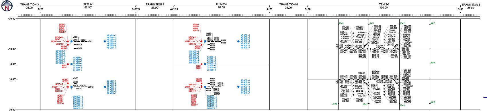
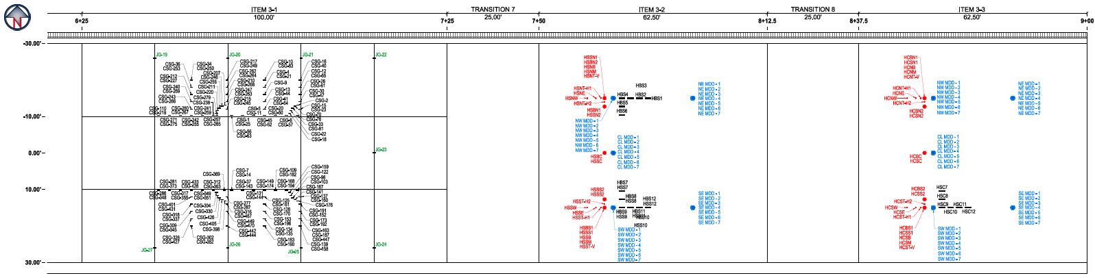
Each of the six flexible pavement test items had three sets of dynamic sensors. The first set consisted of multi depth deflectometers (MDDs), pressure cells (PCs) and asphalt strain gauges (ASGs) in the south traffic path. The second set consisted of the same set of instrumentation in the north traffic path; and the third set consisted of one MDD located in the centerline.
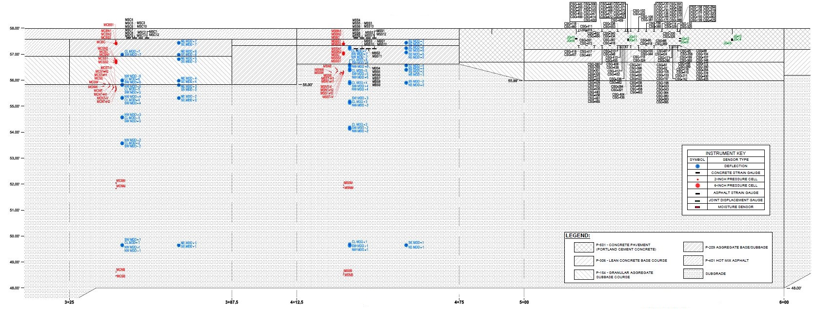
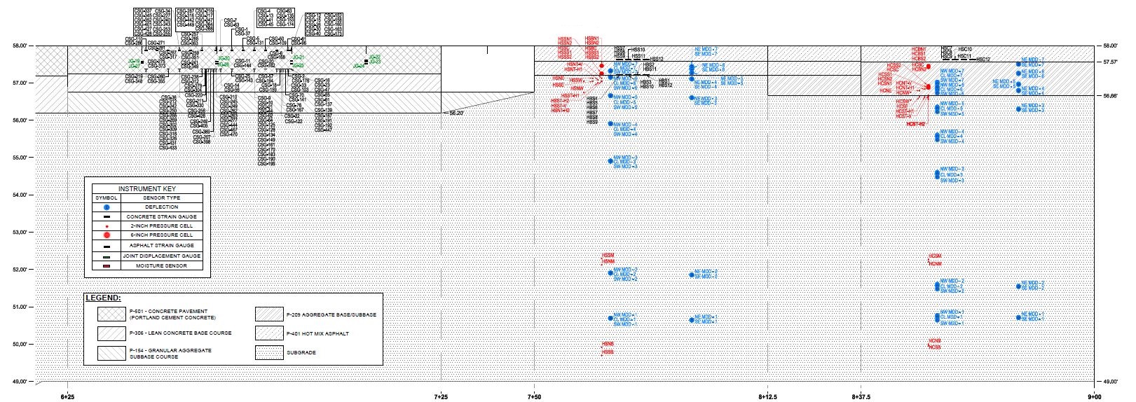
Flexible test items included static sensors in addition to measure the environmental condition of the pavement structure at different levels. Pavement temperatures in the AC layer were monitored using Omega Thermistor temperature gauges. The temperature gauges (TGs) were placed at 0.5-inches (13-mm), 2.5-inches (64-mm), and 4.5-inches (114-mm) below the AC surface. In the case of pavements with asphalt stabilized-base, TGs were placed at the bottom of the asphalt stabilized-base layer.
The flexible pavement test items on conventional base (i.e, LFC, MFC and HFC), had approximately three moisture and six temperature sensors. The flexible pavement test items on stabilized base each had approximately one moisture and ten temperature sensors.
Rigid Pavement
Each rigid pavement test item had also three sets of dynamic sensors. The first set of instrumentation installation consisted of the concrete strain gauges (CSGs) and joint gauges (JGs) in the south traffic path. The second set of instrumentation installation consisted of the CSGs and JGs in the north traffic path, and the third instrumentation installation consisted of a single JG in the centerline.
The rigid pavement test items each had one moisture and six temperature sensors. Additionally, each of the three rigid pavement test items had approximately thirteen resistance sensors to identify when the Econocrete base cracked.
Data Collection
Data was acquired, processed, stored and disseminated from the individual sensors using 6 Hewlett Packard VXI Mainframe Signal Processing Units (SPU) interconnected by wire and wireless local area networks.
Each SPU had a 133- MHz Pentium computer system card and three analog to digital converter (ADC) cards with a 64-channel multiplexer on each card. Each rigid test item had a dedicated SPU. Each pair of flexible test items on a given strength subgrade had a dedicated SPU. The schematic for data collection is shown in the figure below.
The High Speed Data Acquisition System (HSDAS) was used to collect data from the dynamic pavement sensors and transmit the data to a computer located within a control room within the NAPTF.
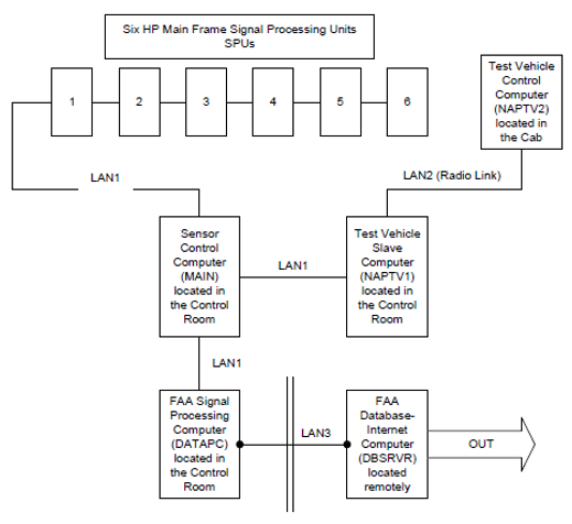
HSDAS Schematic (Click to Zoom)
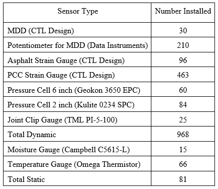
The types and quantity of each gauge installed in CC1 are presented in the table below.
For a pdf of the CC1 Project Instrumentation click here.
For a table of sensor coordinates for each test section reference Sheet 7, 9 and 11 of 12 of the CC1 Historic Drawings linked above.
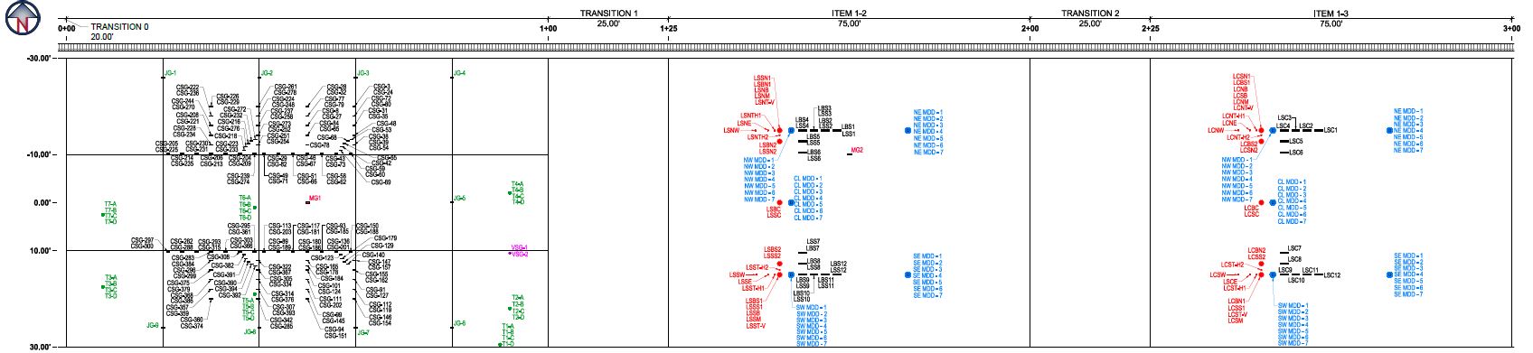
CC1 Instrumentation (Click to Zoom)
For more information on the Instrumentation Plan for each test section click on the links in the table below.
CC1 Low Strength Subgrade
CC1 Low Strength Subgrade Instrumentation Plan View (Click to Zoom)
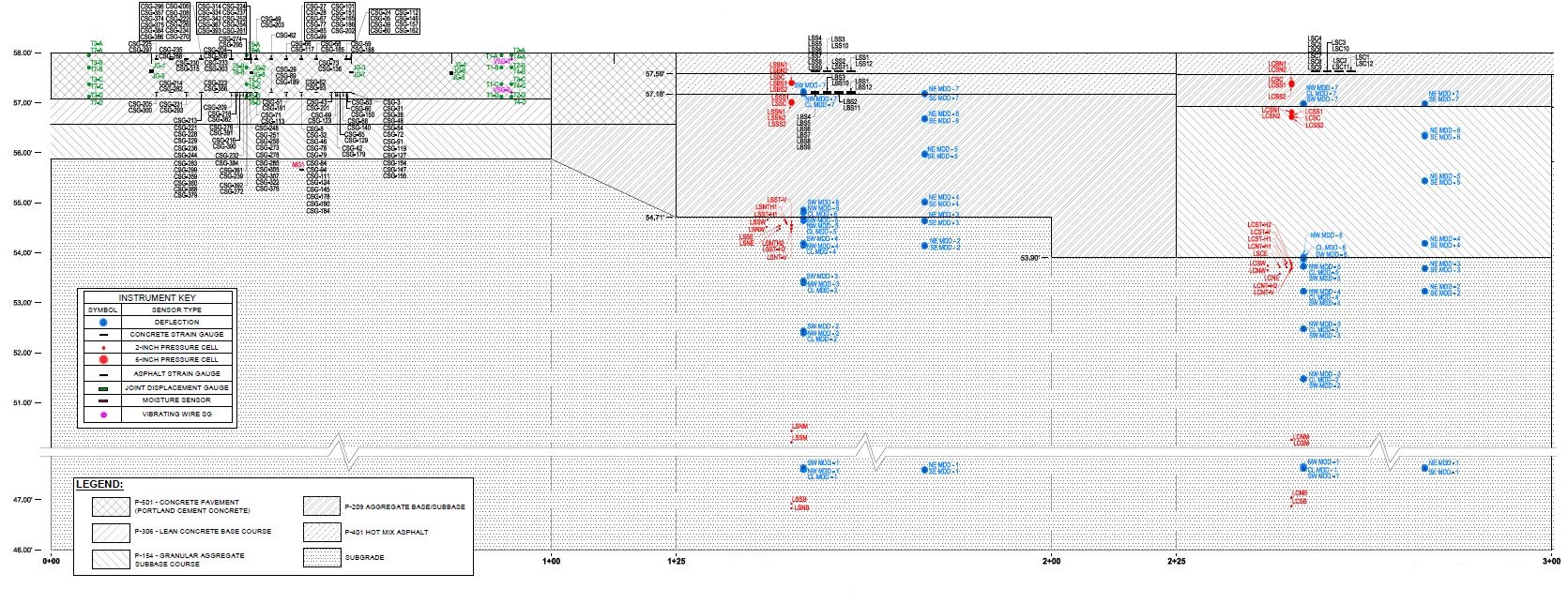
CC1 Low Strength Subgrade Instrumentation Profile View (Click to Zoom)
CC1 Medium Strength Subgrade
CC1 Medium Strength Subgrade Instrumentation Plan View (Click to Zoom)
CC1 Medium Strength Subgrade Instrumentation Profile View (Click to Zoom)
CC1 High Strength Subgrade
CC1 High Strength Subgrade Instrumentation Plan View (Click to Zoom)
CC1 High Strength Subgrade Instrumentation Profile View (Click to Zoom)
Return to Construction Cycle 1 Overview