CC1 Pavement Construction/Cross-Section
To meet the test objectives, the FAA project team drafted a conceptual design for three test sections within CC1 with different subgrade strengths characterized as low (target CBR 4); medium (target CBR 8) and high (target CBR 20). The three test sections included:
- Section 1 – Low Strength Subgrade
- Section 2 – Medium Strength Subgrade
- Section 3 – High Strength Subgrade
An overview of the CC1 Plan and Profile View can be seen below. For a pdf version of the CC1 Historic Drawings click here.
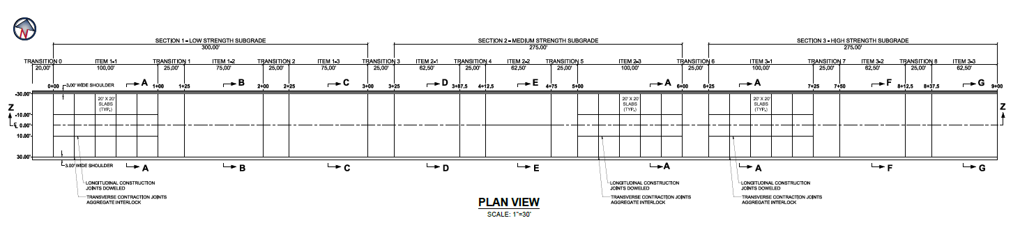
CC1 Plan View (Click to Zoom)
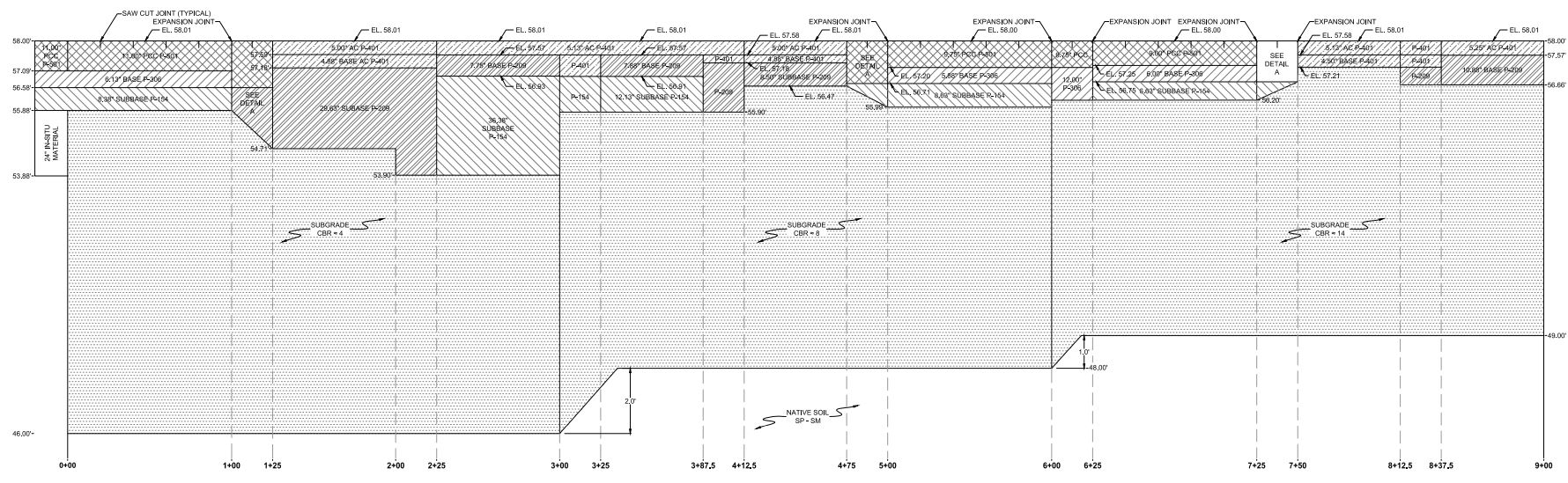
CC1 Profile View (Click to Zoom)
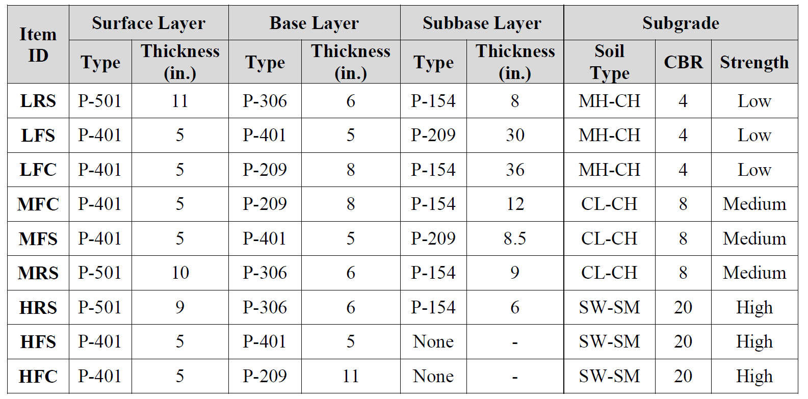
Within the three sections were nine test items; six flexible and three rigid. The flexible test items were either stabilized (asphalt on P-401 asphalt stabilized base) or conventional (asphalt on P-209 crushed aggregate base). The rigid pavement test items were constructed on P-306 Econocrete base. The table below lists the test item designations. The specifications for the materials used were based on the FAA advisory circular AC 150/5370-10A.
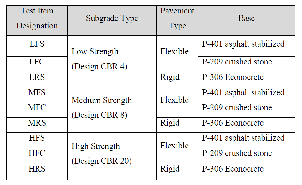
CC1 Test Items Designations (Click to Zoom)
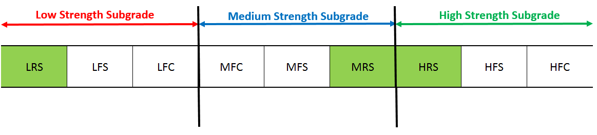
The test items designations include three characters. The first character indicates the subgrade strength: 'L' for low, 'M' for medium, and 'H' for high. The second character indicates the test pavement type: 'F' for flexible and 'R' for rigid. The third character specifies either 'S' for asphalt stabilized or 'C' for conventional base. The figure below illustrates the three different test items and corresponding cross sectional details. North and south sides of the test items were subjected to different traffic loading while having similar structures.
CC1 Test Items Plan View (Click to Zoom)
CC1 Cross Sectional Detail (Click to Zoom)
For more information on the Pavement Construction & Cross Section for each test section click on the links in the table below.
CC1 Low Strength Subgrade
The CC1 Low Strength Subgrade test section occupied the area between station (STA) 0+00 and STA 3+00 and Transition 0 (STA 0+00) and Transition 3 (STA 3+00 to 3+25). Transitions were utilized as a way to distinguish test items as well as to allow time for the NAPTV to get up to speed and for the load to stabilize.
Within this section were three test items; low rigid stabilized base (Item 1-1), low flexible stabilized base (Item 1-2), and low flexible conventional base (Item 1-3).
A County Sand and Stone Clay (CS&SC) purchased from County Sand & Stone Inc. in Norma, New Jersey was used for the construction of the Low Strength Subgrade test design. To avoid potential difficulties in the subgrade preparation due to water table proximity, it was decided to elevate the design grade approximately 4-ft. above the existing ground level. All of the in-situ material was removed to a depth of 12-ft. below the new finished pavement grade. In-situ material was also removed for the Medium and High Strength Subgrade test sections accordingly. Subgrade material was placed in 8-inch lifts or thicker and compacted to the required density to achieve the target CBR of 4.
The design thicknesses for the Low Strength Subgrade test items can be seen in the table above.
The width of the section ran from -33 ft. (north side) to +33 ft. (south side), which included 3 ft. of existing subbase shoulders on both sides.
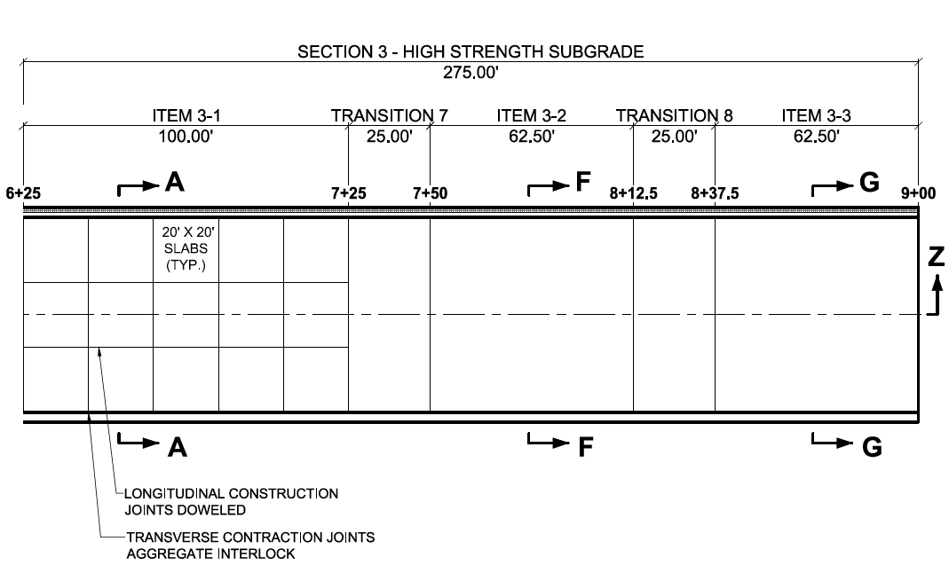
For the rigid test items in CC1, longitudinal joints were placed such that the pattern across the remaining 50-ft. width produced 20-ft. by 20-ft. slabs each on the north and south sides of the test area. The longitudinal joints were construction joint using 1-inch diameter dowels spaced at 10-inches.
All transverse joints were undowelled construction (dummy) joints.
The figures below shows the plan and profile drawings for the CC1 Low Strength Subgrade test section and associated test items.
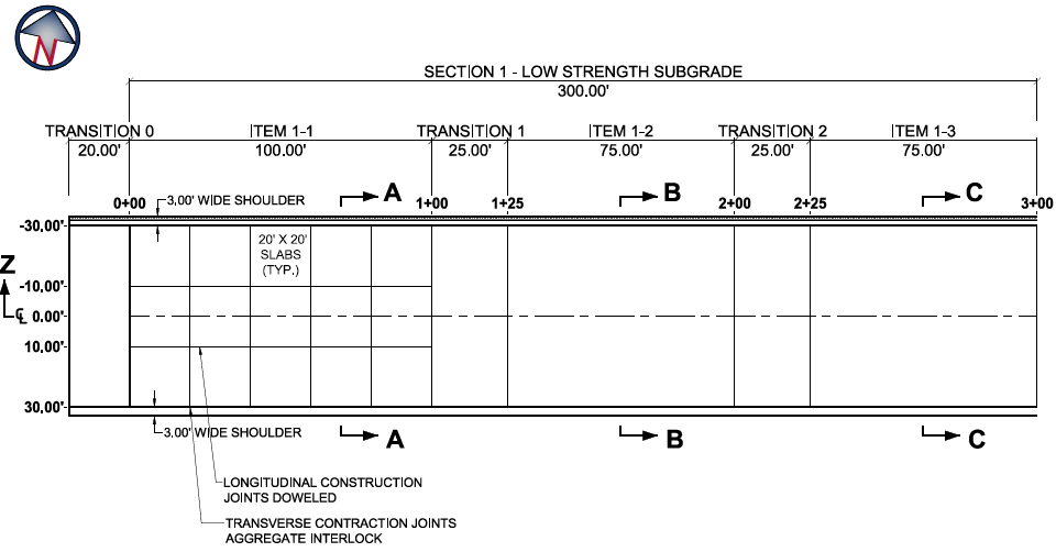
CC1 Low Strength Subgrade Plan View (Click to Zoom)
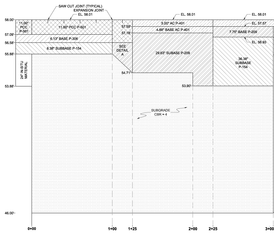
CC1 Low Strength Subgrade Profile View (Click to Zoom)

CC1 Low Rigid Stabilized Base Profile View (Click to Zoom)
.JPG?ver=2018-12-17-110933-957)
CC1 Low Flexible Stabilized Base Profile View (Click to Zoom)
.JPG?ver=2018-12-17-111025-000)
CC1 Low Flexible Conventional Base Profile View (Click to Zoom)
CC1 Medium Strength Subgrade
The CC1 Medium Strength Subgrade test section occupied the area between station (STA) 3+25 and STA 6+00 and Transition 3 (STA 3+00 to 3+25) and Transition 6 (STA 6+00 to 6+25).
Within this section were three test items; medium flexible conventional base (Item 2-1), medium flexible stabilized base (Item 2-2), and medium rigid stabilized base (Item 2-3).
A DuPont Clay material sourced from Woodstown, New Jersey was used for the construction of the Medium Strength Subgrade test design. Construction of the test bed subgrade for the test pavement consisted of removal of the in-situ material to a depth of 10-ft below the new finished pavement grade. Subgrade material was placed in 8-inch lifts or thicker and compacted to the required density to achieve the target CBR of 8.
The design thicknesses for the Medium Strength Subgrade test items can be seen in the table above.
The width of the section ran from -33 ft. (north side) to +33 ft. (south side), which included 3 ft. of existing subbase shoulders on both sides.
The figures below shows the plan and profile drawings for the CC1 Medium Strength Subgrade test section and associated test items.
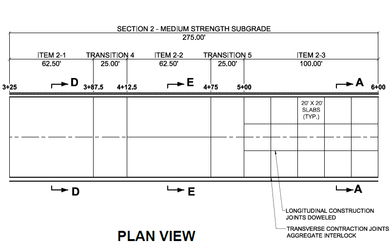
CC1 Medium Strength Subgrade Plan View (Click to Zoom)
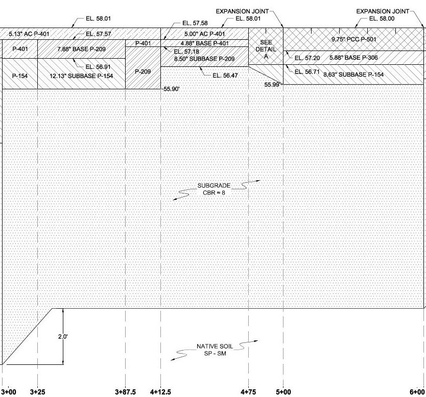
CC1 Medium Strength Subgrade Profile View (Click to Zoom)
.JPG?ver=2018-12-17-111221-100)
CC1 Medium Flexible Conventional Base Profile View (Click to Zoom)
.JPG?ver=2018-12-17-111221-427)
CC1 Medium Flexible Stabilized Base Profile View (Click to Zoom)
CC1 Medium Rigid Stabilized Base Profile View (Click to Zoom)
CC1 High Strength Subgrade
The CC1 High Strength Subgrade test section occupied the area between station (STA) 6+25 and STA 9+00.
Within this section were three test items; high rigid stabilized base (Item 3-1), high flexible stabilized base (Item 3-2), and high flexible conventional base (Item 3-3).
A locally available sand material was used for the construction of the High Strength Subgrade test design. Construction of the test bed subgrade for the test pavement consisted of removal of the in-situ material to a depth of 9-ft below the new finished pavement grade. Subgrade material was placed in 8-inch lifts or thicker and compacted to the required density to achieve the target CBR of 20.
The design thicknesses for the High Strength Subgrade test items can be seen in the table above.
The width of the section ran from -33 ft. (north side) to +33 ft. (south side), which included 3 ft. of existing subbase shoulders on both sides.
The figures below shows the plan and profile drawings for the CC1 High Strength Subgrade test section and associated test items.
CC1 High Strength Subgrade Plan View (Click to Zoom)
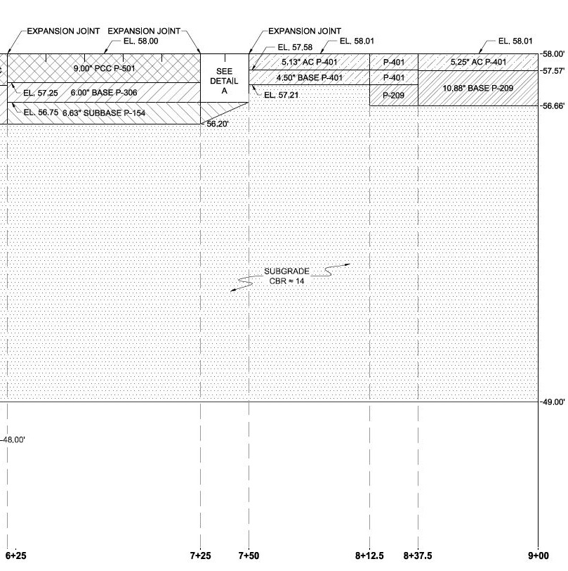
CC1 High Strength Subgrade Profile View (Click to Zoom)
CC1 High Rigid Stabilized Base Profile View (Click to Zoom)
.JPG?ver=2018-12-17-111749-470)
CC1 High Flexible Stabilized Base Profile View (Click to Zoom)
.JPG?ver=2018-12-17-111749-940)
CC1 High Flexible Conventional Base Profile View (Click to Zoom)
Return to Construction Cycle 1 Overview