Pavement Construction & Cross Section
To meet the test objectives, the FAA project team drafted a conceptual design for four test areas to be constructed within CC9. Each test area was designed to meet the selected testing objective(s). The test areas are:
- Fatigue Model and Base Course Thickness
- Geosynthetics
- Cement Treated Permeable Base (CTPB)
- Overload
Pavement design software such as FAARFIED was not used explicitly in determining the thicknesses of the various pavement materials within the test section of CC9, as was done in previous CCs. Thicknesses were chosen based on the objectives, general guidelines from the FAA specifications, and the pavement knowledge of the Project Team that would best suit each experiment. FAARFIELD v1.4, the latest version of the FAA’s pavement design software, was used to estimate the number of vehicle passes until failure. For the Fatigue Model and Base Course Thickness, Geosynthetics, and CTPB test areas, the Airbus A380 was used as a basis for the gear configuration and load. The Overload test section used different gear parameters to remain consistent with CC7’s overload testing.
The total section length for CC9 is 315 feet, from station 0-20 to 2+95. The total section width stretched from offset -31.5 ft. (North side) to +33 ft. (South side), where widths beyond 30 feet are considered pavement shoulders.
The plan and profile views of CC9 As-Builts can be seen below. For a pdf version of the CC9 As-Built drawings click here.
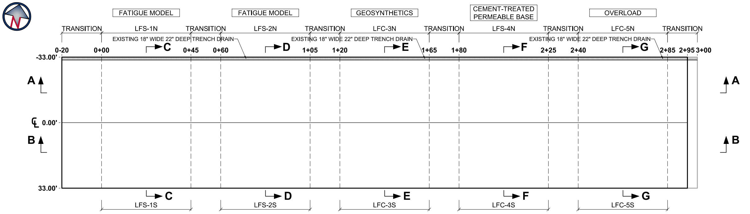
CC9 Plan View (Click to Zoom)
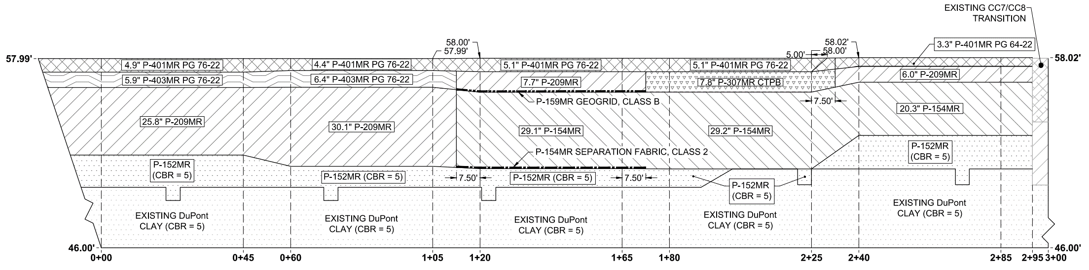
CC9 Profile View - North Side - Section AA (Click to Zoom)
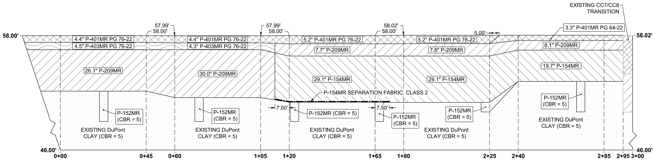
CC9 Profile View - South Side - Section BB (Click to Zoom)
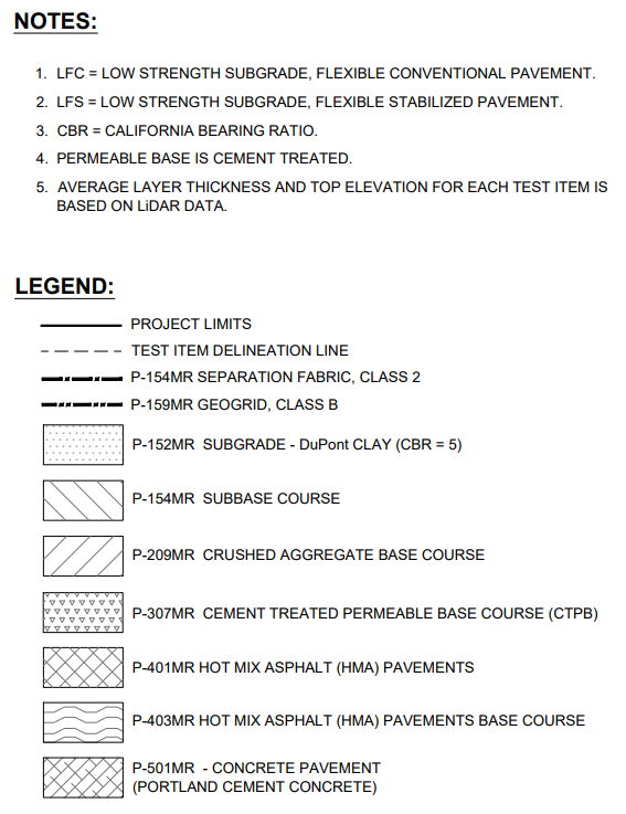
Pavement Legend (Click to Zoom)
For more information on the Pavement Construction and Cross Section for each experiment click on the links in the table below.
CC9 Fatigue Model and Base Course Thickness Test Area
Construction for the Fatigue Model and Base Course Thickness test area included demolition of the existing CC7 flexible pavement structure, conditioning of the in-situ P-152MR subgrade to a target CBR of 5% and placement of 2 lifts of pre-conditioned material, placement of 5 lifts of P-209MR base, placement of 2 lifts of P-403MR asphalt base, and placement of 4 lifts of P-401MR asphalt surface course PG 76-22.
The Fatigue Model and Base Course Thickness test area was constructed from station 0-20 to 1+13 and consists of four flexible test items: LFS-1N and LFS-1S running from station 0+00 to 0+45, and LFS-2N and LFS-2S running from station 0+60 to 1+05, with a transition section in between.
The design thicknesses for the Fatigue Model and Base Course Thickness test area have four differing configurations of base materials. P-209MR was designed 26 inches thick on items 1N and 1S, and 30 inches thick on items 2N and 2S. P-403MR was designed 7 inches thick on items 1N and 2N, and 5 inches thick on items 1S and 2S. All four items were surfaced with 4 inches of P-401MR.
The figures below show the as-built plan and profile for the Fatigue Model and Base Course Thickness test area. (Due to construction variance, as-built elevations may slightly differ from the design.)
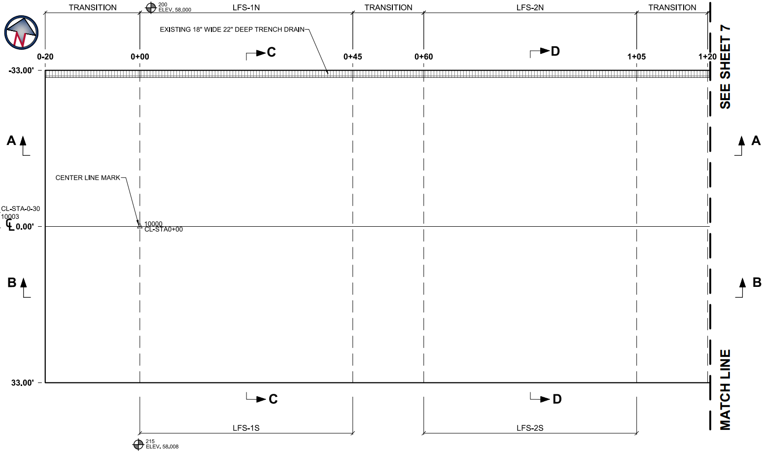
CC9 Fatigue Model and Base Course Thickness Plan View (Click to Zoom)
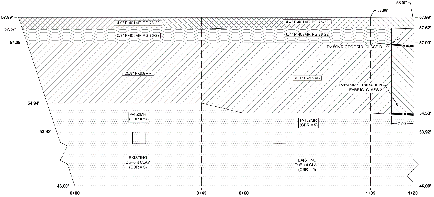
CC9 Fatigue Model and Base Course Thickness Profile View - North Side (Click to Zoom)
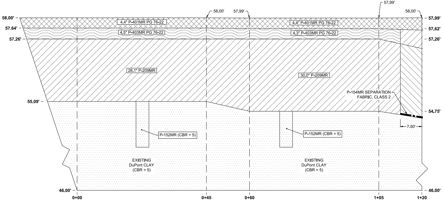
CC9 Fatigue Model and Base Course Thickness Profile View - South Side (Click to Zoom)
CC9 Geosynthetics Test Area
Construction for the Geosynthetics test area included demolition of the existing CC7 flexible pavement structure, conditioning of the in-situ P-152MR subgrade to a target CBR of 5% and placement of 1 lift of pre-conditioned material, placement of P-154MR separation fabric, placement of 4 lifts of P-154MR subbase, placement of P-159MR Geogrid, placement of 1 lifts of P-209MR base, and placement of 2 lifts of P-401MR asphalt surface course PG 76-22.
The Geosynthetics test area was constructed from station 1+13 to 1+73 and consists of two flexible test items, LFC-3N and LFC-3S, that run from station 1+20 to 1+65. The area outside of those items are transition sections.
The design thicknesses for the Geosynthetics test area are identical for both test items, with 29 inches of P-154MR, 8 inches of P-209MR, and 5 inches of P-401MR. A P-154MR separation fabric was also placed on top of the subgrade. The only difference between the items is that item 3N has a P-159MR Geogrid placed on the P-154MR.
The figures below show the as-built plan and profile for the Geosynthetics test area. (Due to construction variance, as-built elevations may slightly differ from the design.)
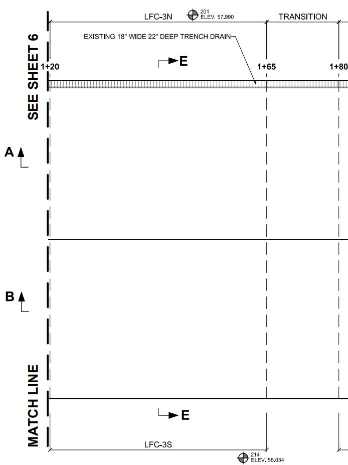
CC9 Geosynthetics Plan View (Click to Zoom)
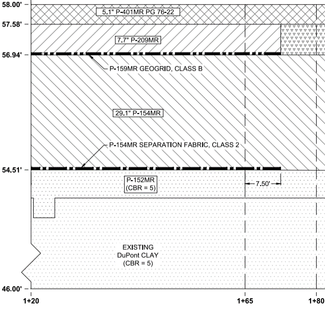
CC9 Geosynthetics Profile View - North Side (Click to Zoom)
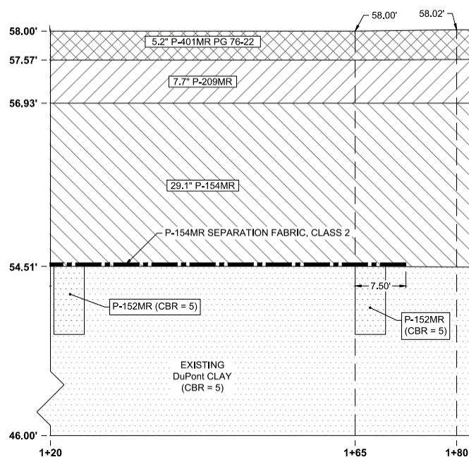
CC9 Geosynthetics Profile View - South Side (Click to Zoom)
CC9 Cement Treated Permeable Base (CTPB) Test Area
Construction for the CTPB test area included demolition of the existing CC7 flexible pavement structure, conditioning of the in-situ P-152MR subgrade to a target CBR of 5% and placement of 1 lift of pre-conditioned material, placement of 4 lifts of P-154MR subbase, placement of 1 lift of P-209MR base and P-307MR base, and placement of 2 lifts of P-401MR asphalt surface course PG 76-22.
The CTPB test area was constructed from station 1+73 to 2+33 and consists of two flexible test items, LFC-4N and LFC-4S, that run from station 1+10 to 2+25. The area outside of those items are transition sections.
The design thicknesses for the CTPB test area are identical for both test items, with one material change. Both were designed to have 29 inches of P-154MR, 8 inches of base material, and 5 inches of P-401MR. Test item 4S had a standard P-209MR base material, while item 4N had P-307MR as base material.
The figures below show the as-built plan and profile for the CTPB test area. (Due to construction variance, as-built elevations may slightly differ from the design.)
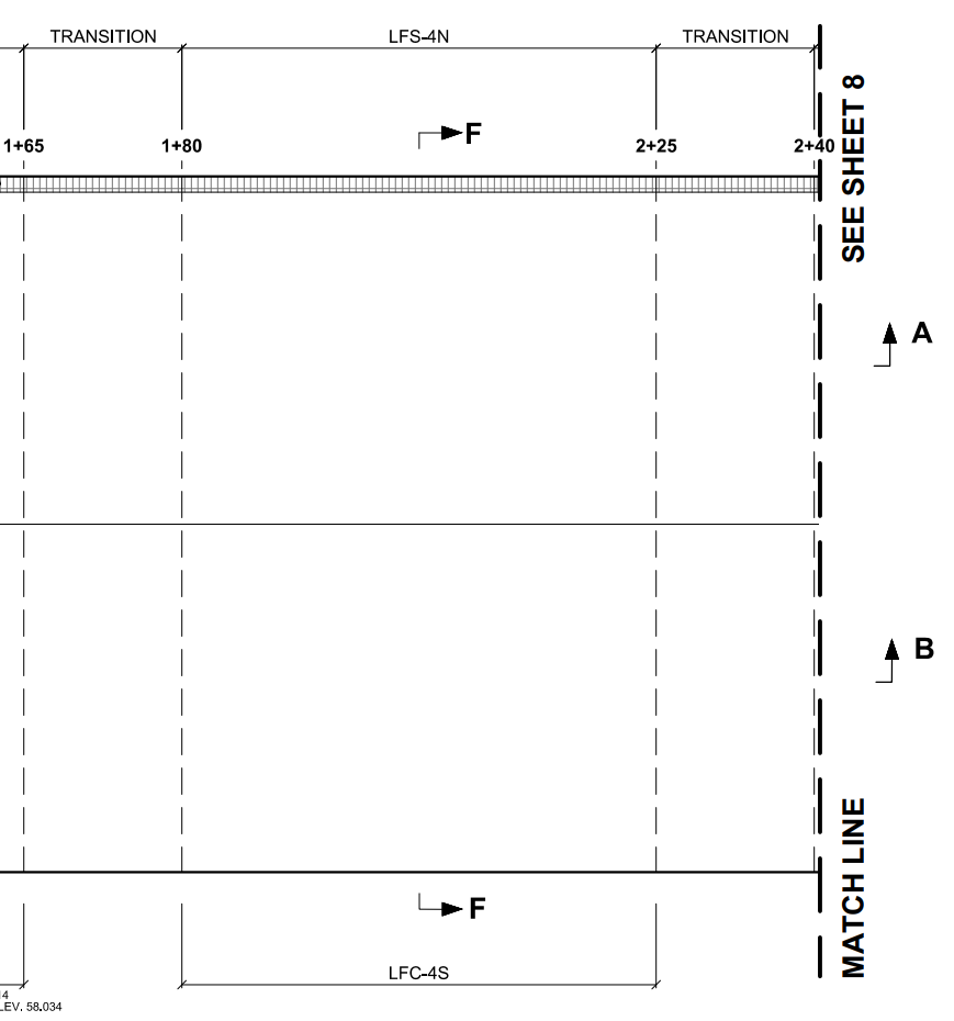
CC9 CTPB Plan View (Click to Zoom)
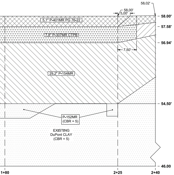
CC9 CTPB Profile View - North Side (Click to Zoom)
CC9 CTPB Profile View - South Side (Click to Zoom)
Overload Test Area
Construction for the Overload test area included demolition of the existing CC7 flexible pavement structure, conditioning of the in-situ P-152MR subgrade to a target CBR of 5% and placement of 2 lifts of pre-conditioned material, placement of 3 lifts of P-154MR subbase, placement of 1 lift of P-209MR base, and placement of 1 lift of P-401MR asphalt surface course PG 64-22.
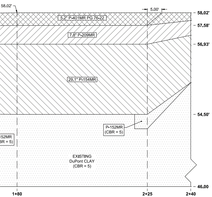
The Overload test area was constructed from station 2+33 to 2+95 and consists of two flexible test items, LFC-5N and LFC-5S, that run from station 2+40 to 2+85. The area outside of those items are transition sections.
The design thicknesses for the Overload test area are identical for both test items. Both were designed to have 20 inches of P-154MR, 6 inches of P-209MR, and 3 inches of P-401MR.
The figures below show the as-built plan and profile for the Overload test area. (Due to construction variance, as-built elevations may slightly differ from the design.)
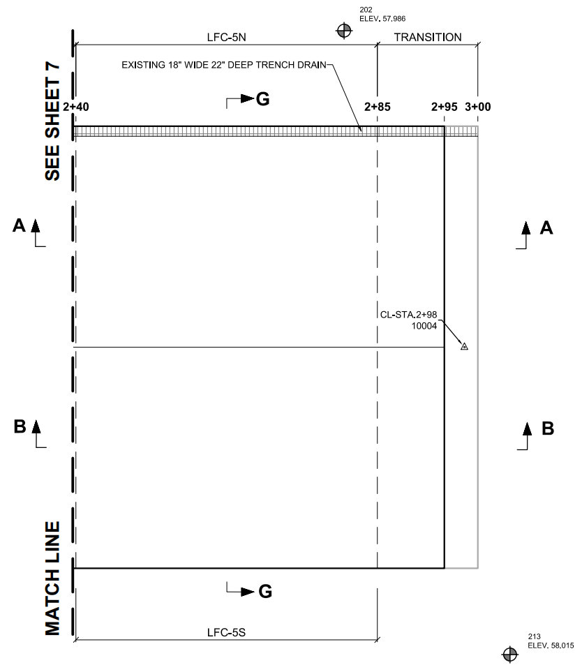
CC9 Overload Plan View (Click to Zoom)
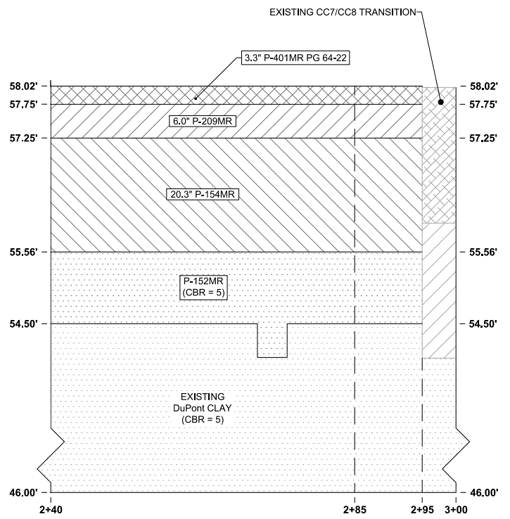
CC9 Overload Profile View - North Side (Click to Zoom)
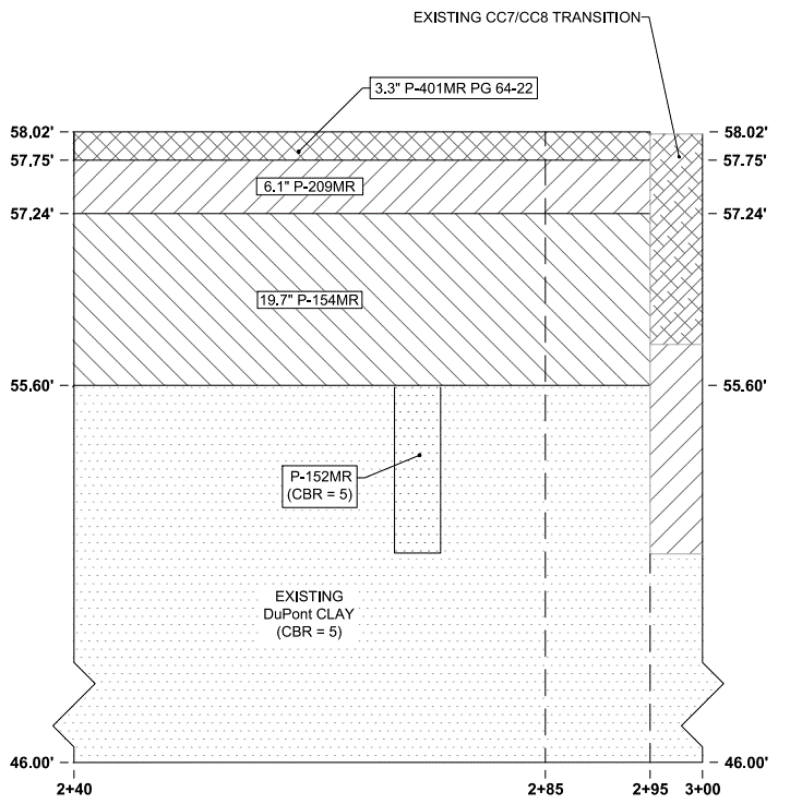
CC9 Overload Profile View - South Side (Click to Zoom)
Return to Construction Cycle 9 Overview