3D Scanning
 !?
!?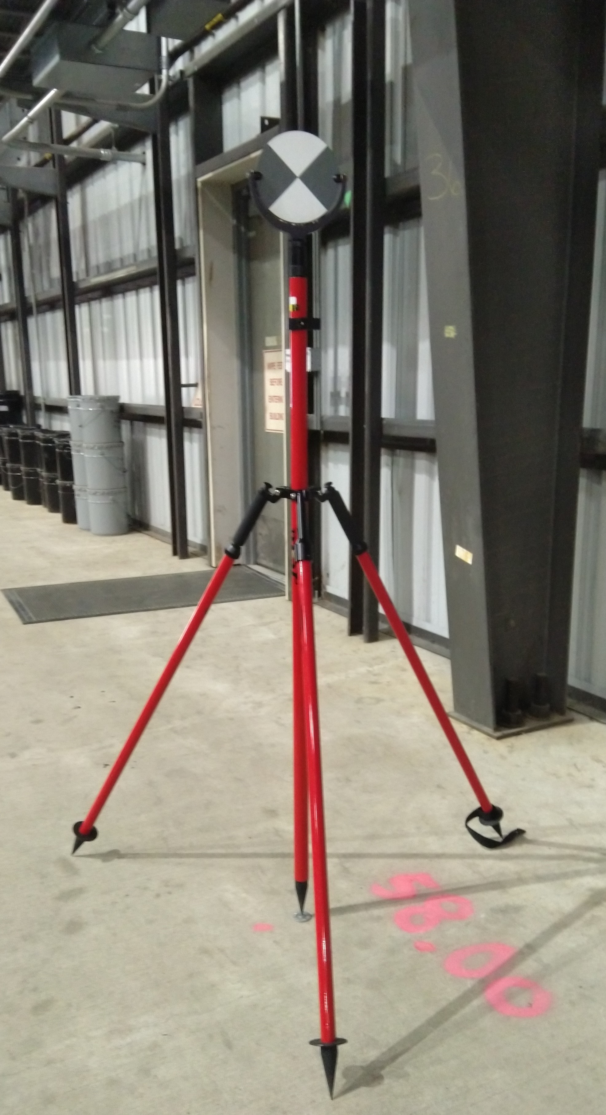
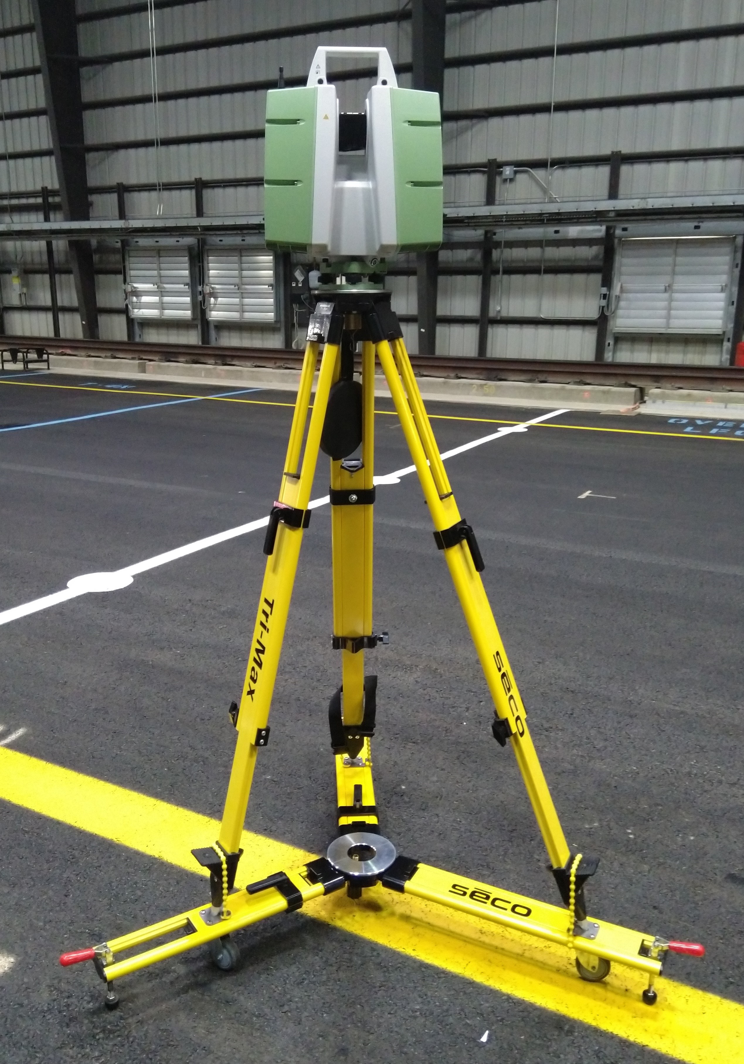
3D Scanner (Left) and a Target (Right) (Click to Zoom)
The 3D scanning system combines various imaging technologies in a single device to create a point scan of an entire area. Such devices are capable of scanning thousands of points every second with high accuracy and precision. With analysis, 3D scanning can accomplish the same tasks as other profiling devices like the walk-behind surface profiler or distress measuring devices such as the straightedge. 3D scanning is especially useful for construction acceptance and quality assurance, able to produce maps of elevation and pavement thickness for comparison to the project’s requirements.
The system consists of the device itself and separate targets. The 3D scanner is mounted onto a tripod and/or a dolly and positioned as desired. Targets are placed around the site as reference points. The scanner itself consists of the scanning element, level/tribrach and plummet, touchscreen, and internal storage/computer. The scanning element contains a dual-axis rotating mirror with laser and camera aperture. The stand and base allow for high freedom of movement, with the scanner able to rotate around fully and cover the majority of the space vertically, excluding the area covered by its base.
Prior to a scan, operators position the scanner and the targets, aiming the targets at the scanner. Positioning either the scanner or the targets at known locations allows for georeferencing. Scan area and quality are set by the user. During a scan, the device takes a full point map then collects pictures of the area. After a scan is complete, the operators identify and scan each of the targets separately. As data is taken further away from the scanner, the distance between each point increases and the accuracy decreases. Multiple overlapping scans are taken throughout the test area to ensure accuracy.
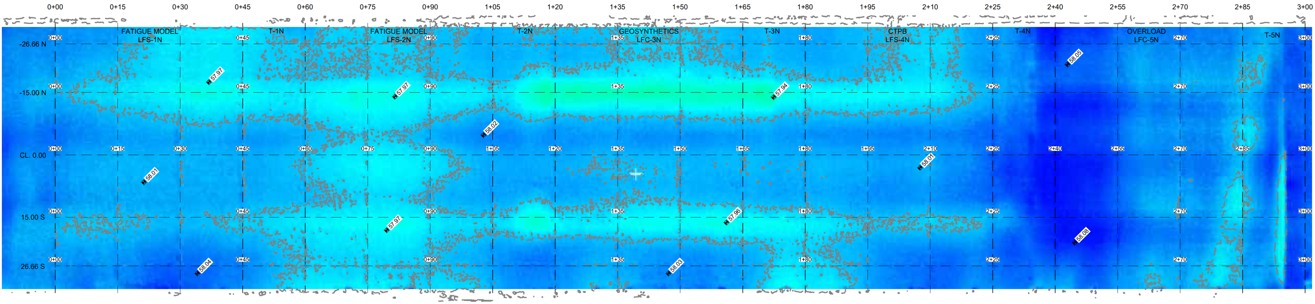
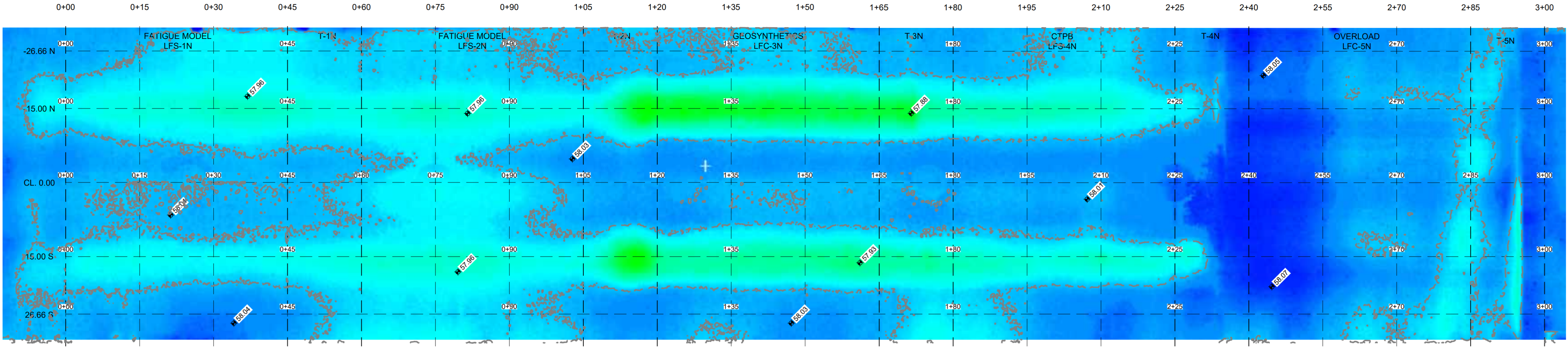
Specialized software is used to process and analyze the 3D scan data. First, a high resolution point cloud is created by combining the point and image data. Point data includes 3-axis coordinates, intensity, and color. The cloud can be further used to create various maps, including 2D CAD drawings, 3D models, elevation heatmaps (shown below), construction conformance maps, deformation distress identification for rutting and upheaval, and profile lines (shown below). It can also be used to calculate cut and fill volumes, which is useful in the site/civil and construction fields.
CC9 on April 9, 2021 (330 passes)
CC9 on May 19, 2021 (3,234 passes)
Sample Elevation Heatmap from 3D Scanning (Click to Zoom)
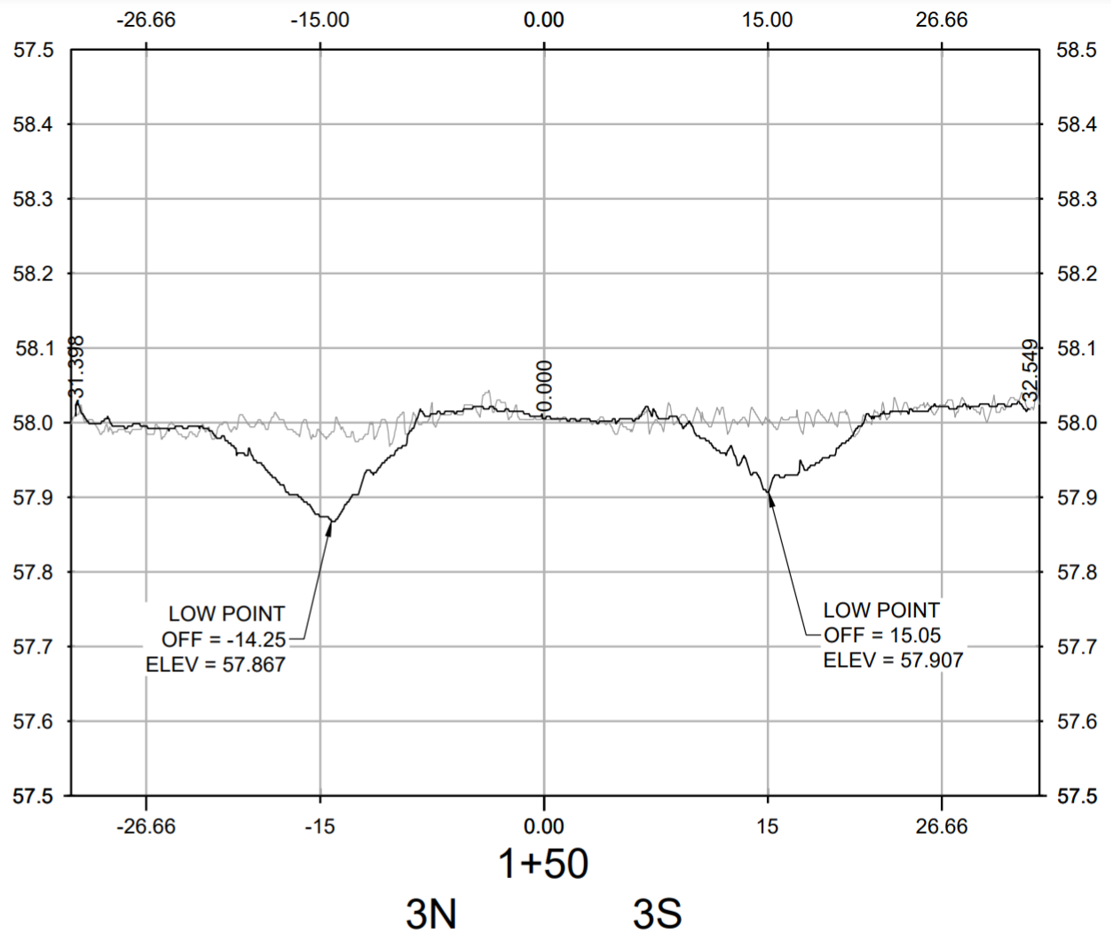
CC9 Station 1+50 on May 19, 2021 (3,234 passes)
Sample Elevation Profile from 3D Scanning (Click to Zoom)
3D scanning is best used in field applications, and is ideal in situations where determining elevation over a large area is desired. Such results would not be possible to produce with other elevation measuring devices due to the time investment required.
For more information on the devices mentioned on this page, follow the links to the detailed FAA webpages.
Walk-Behind Surface Profiler
Straightedge
Return to NDT Technology Overview