Ground Penetrating Radar (GPR)
Ground penetrating radar (GPR) is an electromagnetic device used to investigate the subsurface conditions of a structure by transmitting electromagnetic signals into the surface and measuring the resulting reflected signals. This technology can be used for a variety of civil engineering applications, including the determination of pavement layer thickness and the location and characterization of embedded objects, such as rebars and conduits.
The system consists of an antenna, a control unit, a distance measuring instrument (DMI), and a computer. The control unit is an electronic device that transmits and receives electromagnetic signals through the antenna and converts them for display and interpretation. The DMI measures the horizontal distance traveled by the system and triggers the data acquisition at specified intervals. The computer displays and records the data as it is collected.
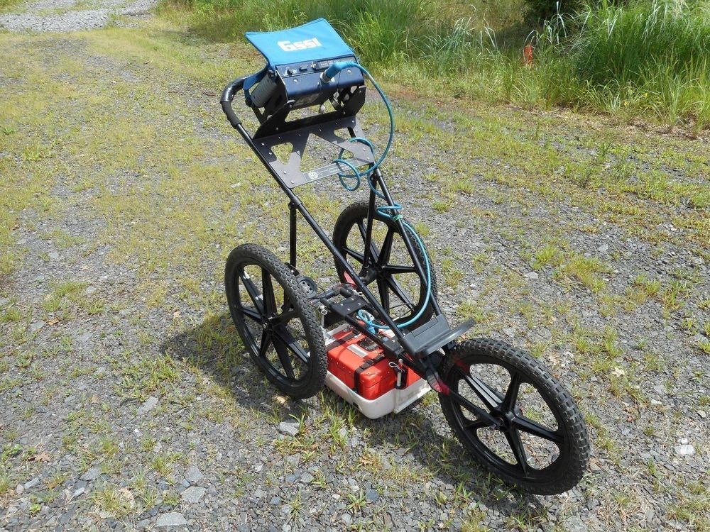
There are two types of GPR antenna: air-coupled and ground-coupled. An air-coupled antenna is suspended above the ground surface, usually mounted on a vehicle, and is capable of traveling at higher speeds, making it ideal for surveys of large areas. A ground-coupled antenna maintains contact with the ground, usually mounted in a push-cart, and is ideal for in-depth investigation of smaller areas. The classification of an antenna is based on its operating frequency. In general, a higher frequency antenna produces signals with shorter wavelengths, capable of higher resolution, but less depth penetration. A lower frequency antenna produces signal with longer wavelengths, capable of deeper depth penetration, but of lower resolution.
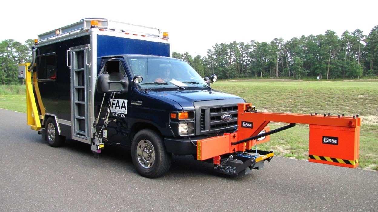
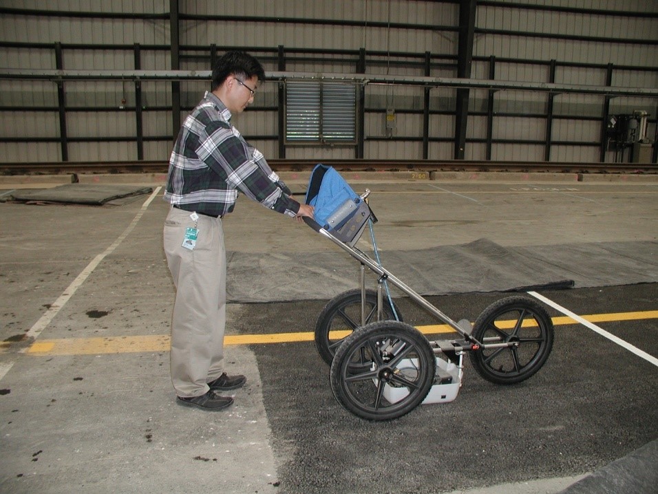
Air- and Ground-Coupled GPR Mounted on FAA NDT Van (left) and Ground-Coupled GPR Mounted on Push-Cart (right) (Click to Zoom)
Detection of objects using GPR is based on the contrast of dielectric constants between materials. The dielectric constant, or relative permittivity, of a material is a measure of how much it will polarize when exposed to an electrical field. A material with a low dielectric constant, such as air, will polarize very little, allowing an electromagnetic wave to pass through it. A material with a high dielectric constant, such as metal, will polarize heavily, blocking an electromagnetic wave from passing through it. A GPR survey is conducted along a scan line where the DMI triggers data collection at a specified frequency. Each time the system is triggered, it broadcasts an electromagnetic wave into the surface. This wave is reflected and refracted at material boundaries, such as pavement layer interfaces and embedded objects, based on the difference in dielectric constant values between materials, and the reflected wave is recorded in terms of amplitude and two-way travel time. The depth to the object is calculated based on the wave velocity in the material, which is derived from the material dielectric constant. The scans are stacked to form a depth profile along the survey path with signal attenuation depicted in greyscale, as shown below.
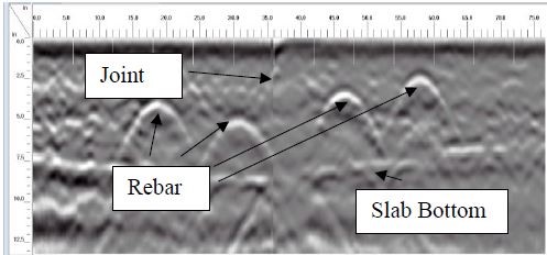
GPR Imaging of Longitudinal Joint of a Rigid Pavement Taxiway with Joint, Rebar, and Slab Bottom Visible (Click to Zoom)
An air-coupled GPR system mounted onto a vehicle is ideal for surveys of large areas, such as airport runways, while a ground-coupled system mounted onto a push-cart is ideal for in-depth investigation of small areas of interest. Depending on the investigation needs, the user can conduct the GPR survey in a relatively short amount of time either in the field or laboratory test beds.
Return to NDT Technology Overview