CC7 Trenching Plan
Trenching provided a viable option to examine failed test items, confirm the contribution of each pavement layer to the total rutting, characterize material properties for each layer of the pavement structure, evaluate the effect of traffic load on the material properties, retrieve and preserve samples for laboratory material characterization.
One 60-foot long by 4-foot wide trench was excavated perpendicular to the centerline of the NAPTF for each test item. Trenches in test items LFC5-N, LFS6-N, LFC5- S and LFC6-S were excavated to an approximate depth of 49 inches, including the removal of the P-154/P-152 interface. All remaining trenches in both north and south side were excavated to an approximate depth of 54 inches. The table below lists the start and end station for each trench. These trenches were located between the MDD sensors and profile stations where the maximum rut depth was measured (see figures below).
Summary of Trench Locations
|
Test Item
|
Start STA, ft
|
End STA, ft
|
|
LFP1-N/LFC1-S
|
20.5
|
25.0
|
|
LFP2-N/LFC2-S
|
70.5
|
75.0
|
|
LFP3-N/LFC3-S
|
120.5
|
125.0
|
|
LFP4-N/LFC4-S
|
165.0
|
169.5
|
|
LFP5-N/LFC5-S
|
220.6
|
225.0
|
|
LFP6-N/LFC6-S
|
270.6
|
275.0
|
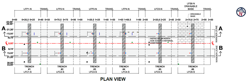
Plan View of Trench Locations (Click to Zoom)
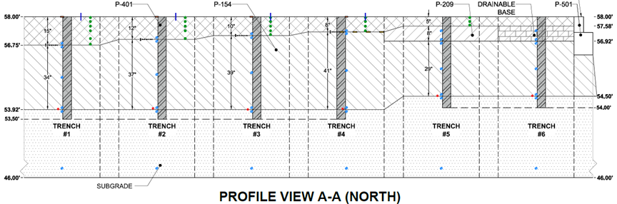
Profile View of Trench Locations (North) (Click to Zoom)
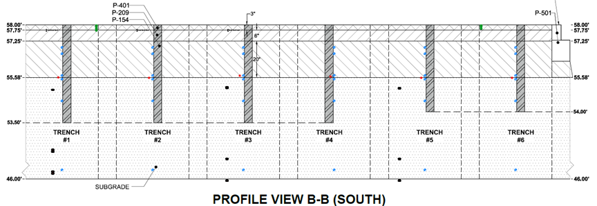
Profile View of Trench Locations (South) (Click to Zoom)
The trenching involved removal of the surface P-401 HMA layer, Asphalt Treated Drainable Base (ATDB), P-209 base, and P-154 subbase (in multiple lifts) to reveal the subgrade interface. Removal of the P-401 layer required a saw cut deep enough to penetrate through the HMA surface, while minimizing the disturbance to base and subbase materials. Field tests and measurements were then performed on the various pavement layers at some or all typical locations shown in the figure below.
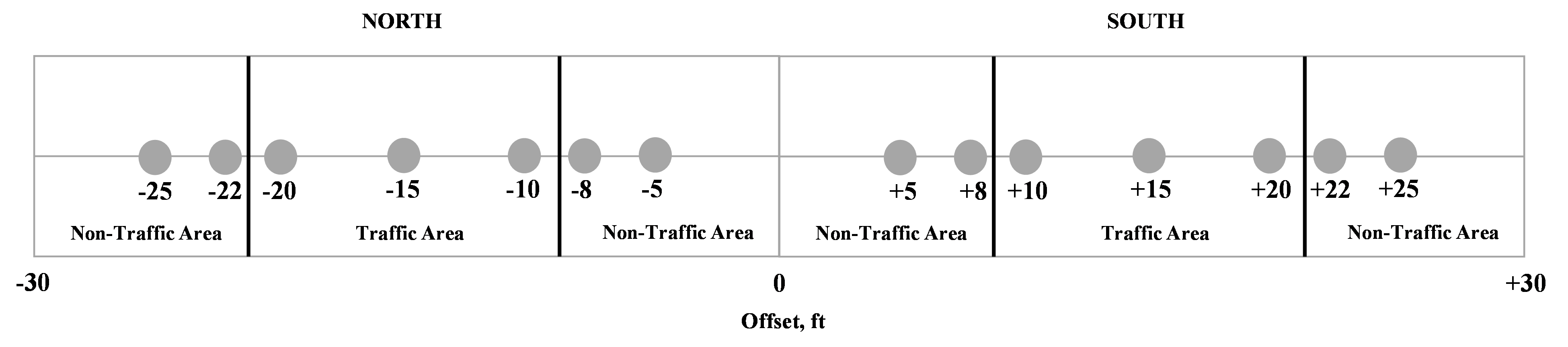
Typical Layout of Test Locations on the Various Pavement Layers (Click to Zoom)
Upon the completion of all field tests, transverse trench walls (at base, subbase and subgrade levels) were smoothed and cleaned using shovels, chisels, and brooms. Then chalk and string lines were used to differentiate pavement layers. The profile of each layer was measured at regular intervals to determine its contribution to the total deformation and upheaval of the test pavement.
To view the CC7 Trenching As-Build Drawing, click here.
To download the CC7 Post Traffic Testing Plan, click here.
To see pictures of the CC7 Post Traffic Testing, click here.
Return to Construction Cycle 7 Overview