Construction Cycle 7 (CC7)
Construction Cycle 7 (CC7) has been the most complex and challenging full-scale experiment ever designed and built at the Federal Aviation Administration (FAA) National Airport Pavement Test Facility (NAPTF). The test pavement was constructed on low-strength subgrade material with a designed California Bearing Ratio (CBR) between 5 and 6. The test pavement was divided into two test areas, North and South, corresponding to a Perpetual Pavement Test and Overload Test respectively. See below for the CC7 overall plan view. To search the CC7 database, click here.
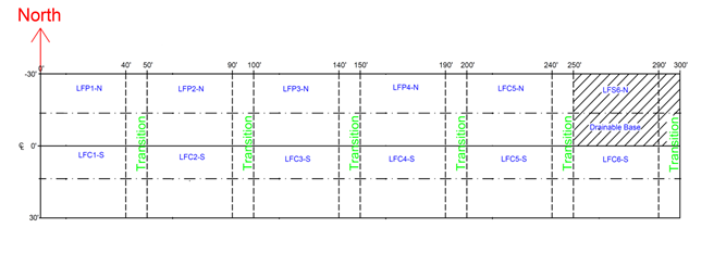
CC7 Overall Plan
North - Perpetual Pavement Test
CC7 North Test Objective
The objective of the Perpetual Pavement Test was to extend the Perpetual Pavement concept to airport pavements. In the perpetual pavement concept, pavement failure is limited to the surface layer while structural failure (rutting in subgrade, bottom-up fatigue cracking) is eliminated.
The test objectives of the full-scale perpetual test were:
a. Develop a Perpetual Pavements Design criterion for airport pavements.
b. Determine the vertical strain threshold in the Hot Mix Asphalt (HMA) layer to limit rutting.
c. Determine the horizontal strain threshold at the bottom of the HMA layer to prevent bottom-up fatigue cracking.
d. Determine the relationship between laboratory fatigue strain thresholds and measured field HMA strains.
e. Study the strain distribution within the HMA layer.
CC7 North Pavement Construction/Cross Section
CC7 North consisted of six test items 40 feet long and 33 feet wide with six 10-foot long transition areas between Stations 0+00 and 3+00. The six test items were composed of a clay subgrade material with a design CBR of 5.5, a variable thickness layer of P-154 subbase, and a variable thickness surface layer of P-401 asphalt. Test items LFP1-N to LFP4-N were designated as perpetual test items. The remaining two test items, LFC5-N and LFS6-N, had additional base layers. LFC5-N had an 8 inch P-209 aggregate base layer while LFS6-N had an 8 inch asphalt treated drainable base (ATDB) layer. The test items were designed using FAARFIELD (FAA 2016). The pavement structures are shown in the figure below.
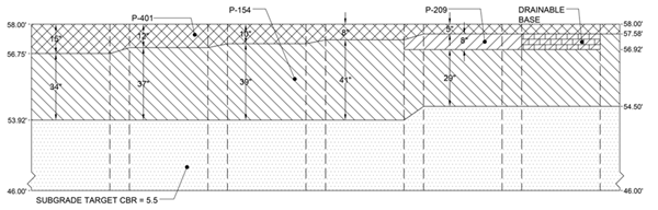
Click here to download the CC7 Perpetual Pavement Test (North) Profile
CC7 North Traffic Test Results
Full-scale traffic testing began on 09/15/2014 using the National Airport Pavement Test Vehicle (NAPTV) with a six-wheel (3D) configuration (55 kips per wheel) at 2.5 mph. The wheel load was increased to 65 kips after 30,030 loading passes.
After completion of 23,364 passes, traffic tests were terminated on test items LFC5-N and LFS6-N. The test sections were declared failed due to the presence of severe fatigue cracking (alligator cracking). Traffic tests continued on the perpetual pavement test sections (LFP1-N through LFP4-N). Traffic tests were terminated on LFP4-N after the completion of 27,192 passes. After completion of 30,030 passes, traffic tests were continued on LFP1-N, LFP2-N, and LFP3-N at an increased wheel load of 65 kips. Traffic tests were terminated on LFP3-N after the completion of 35,046 passes due to the presence of severe fatigue cracking. Traffic tests were terminated on LFP1-N and LFP2-N after the completion of 37,686 passes with no evidence of any fatigue cracking.
For more information on the CC7 North Construction Cycle Experiment click on one of the links in the table below.
Construction (North)
Traffic Testing (North)
Post Traffic Testing (Comprehensive)
To search the CC-7 Database, click here: Search the CC-7 Database
South - Overload Test
CC7 South Test Objective
The objective of the Overload Test was to determine allowable overload criteria for flexible pavements. The current ICAO overload criteria (ICAO, Annex 14) are conservative and unsupported by empirical data. Ideally, allowable overload criteria would be linked to the cumulative damage factor (CDF), which would then allow individual overloads to be related to consumed life.
CC7 South Pavement Construction/Cross Section
The CC7 South test area was designated as the Overload Test and consisted of six test items between Stations 0+00 and 3+00. Each test item was 40 feet (12.2m) long and 33 feet (10.1m) wide, and test items were separated by 10 foot (3m) transition areas as shown in the CC7 Overall Plan at the top of this page. All test items had the same cross section. The cross section consisted of a clay subgrade material with a design CBR of 5, a 20-inch thick layer of P-154 subbase, a 6-inch layer of P-209 aggregate base and a 3-inch thick surface layer of P-401 asphalt. These test items were designed using FAARFIELD. The pavement structure is shown in the figure below.
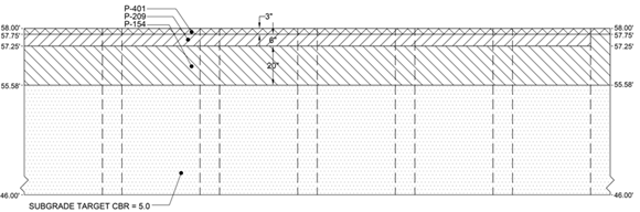
Click here to download the CC7 Overload Test (South) Pavement Profile
CC7 South Traffic Test Results
Full-scale traffic testing began on October 6, 2014 using the NAPTV with multiple gear configurations (D, 2D, and 3D) at 2.5 mph. Overload test items LFC3-S and LFC6-S were the first test items to fail. The failure criterion was approximately one inch (2.5cm) of surface upheaval outside the traffic limits, as in all previous flexible tests at the NAPTF. However, it was observed in LFC3-S and LFC6-S that this criterion coincided with the appearance of extensive longitudinal cracks within the traffic limits, and with them beginning of intersecting (fatigue) cracks, along with deep ruts. Thus, the surface distress was used as an alternate criterion for determining failure in the remaining test items. The traffic test concluded on October 13, 2016, with all test items failed.
For more information on the CC7 South Construction Cycle Experiment click on one of the links in the table below.
Construction (South)
Traffic Testing (South)
Post Traffic Testing (Comprehensive)
To search the CC-7 Database, click here: Search the CC-7 Database