The National Airport Pavement Test Vehicle (NAPTV) is a rail-based test vehicle capable of simulating the heaviest aircraft found in commercial fleets. It was created in response to the development of continuingly complex gear from new generations of aircraft, which exert more pressure on airport pavements. The test vehicle has 20 independently run test wheels - with wheel loads adjustable up to 75,000 pounds (34,019 kilograms) per wheel.
‘Wander’ is the measure of how successive aircraft deviate from runway or taxiway center lines. The NAPTV mimics aircraft wander which is programmable and can operate in manual or fully automatic modes.
The NAPTV weighs approximately 1.3 million pounds (589,670 kg) and is driven by 16 – 50 horsepower electric motors. The test vehicle uses a regenerative braking system to stop, before engaging pneumatic brakes at a full stop. The test vehicle typically travels at 2.5 to 3 miles (4 to 4.8 kilometers) per hour but can reach up to 15 miles (24 kilometers) per hour. During traffic tests the NAPTV operates in full automatic mode. The NAPTV operator inputs the starting and stopping points for the NAPTV, defines where the start and end points are for each test section, and defines the wheel loads, and gear configuration for each test section.
Carriages and Load Modules
The NAPTV is comprised of two carriages that accommodate up to five load modules each. There are two single-wheel load modules and eight dual-wheel load modules, allowing for configurations of up to eighteen wheels with loads up to 75,000 pounds (34,019 kilograms) per wheel.
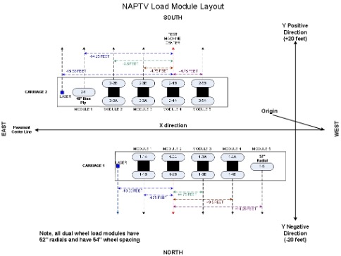
Figure 1. Sample Vehicle Load Module Diagram
The north carriage designation is “Carriage 1” and the south carriage is “Carriage 2”. The east-most load module on each carriage is numbered “1”, while the west-most load module is numbered “5”.
Example: 1-1 is on the north carriage and faces the east-end of the facility. 2-5 is on the south carriage facing the west-end of the facility.
Inner wheels are designated as “A” and are closest to the test facility centerline, while the outer wheels are designated “B”. Typically, the load modules have 52-inch (132 centimeter) radial aircraft tires installed for dual-wheel modules and 49-inch (124 centimeter) bias ply aircraft tire on single-load modules.
Each load module can be operated independently to simulate any desirable configuration. Tandem spacing of the modules can be set by using different lateral mounting positions on the carriage.
The load modules each have their own digital position/force feedback hydraulic control system, which is accomplished by a motion controller to hold position (inches) or load (pounds) on the test pavement. The digital motion controllers receive feedback from module position, hydraulic pressures, and test pavement elevation measurements that are used to extend, hold a load, or retract the load module.
The NAPTV has safety interlocks built into the system that monitor module load, position, and tire pressure. If any of the safety interlocks are triggered, the NAPTV immediately stops, and the horn beeps at a rapid frequency to alert the research team an error is occurring and needs attention.
Vehicle Wander
The NAPTV simulates realistic aircraft wander by varying the lateral position of the carriages to simulate a normal distribution of aircraft. The wander pattern used for most traffic tests consists of 66 NAPTV passes, arranged in nine wander positions (or tracks). The wander positions and sequences are chosen to simulate a normal distribution of aircraft traffic with a standard deviation of 30.5 inches (77.5 centimeters) (representing the current design condition for airport taxiways). Normally, the same wander is used on both carriages, and changed at the west end of the test pavement. Specific wander patterns are published under each construction/traffic testing cycle.
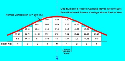
Figure 2. Vehicle Wander Diagram
The carriages use an absolute positioning system which retains its zero, or home position, until it is physically reset by the NAPTV Operator. The test facility centerline serves as the zero position. Wander positions for Carriage 1 range between 0 to -20 feet, and 0 to +20 feet for Carriage 2. The wander position of the carriages is based on the center position of the load module. Position error at any wander position is less than 0.5 of an inch.
Example: A dual-wheel load module at wander position -20 feet means the center of the outer wheels is at -22 feet, 3 inches. The inner wheel would be at -17 feet, 9 inches.