.jpg?ver=2018-03-29-135905-830)
The FAA operates a state-of-the-art, full-scale pavement test facility dedicated solely to airport pavement research. Located at the William J. Hughes Technical Center for Advanced Aerospace near Atlantic City, New Jersey, the National Airport Pavement Test Facility (NAPTF) provides high quality, accelerated test data from rigid and flexible pavements subjected to simulated aircraft traffic. Construction of the facility was completed in April 1999. Major features of the National Airport Pavement Test Facility are:
- Fully enclosed instrumented test track 900 feet long by 60 feet wide.
- Fully automated computerized data acquisition system.
- Rail-based test vehicle capable of simulating aircraft weighing up to 1.3 million pounds.
- Up to 20 test wheels capable of being configured to represent two complete landing gear trucks, each truck having 1 to 10 wheels per truck.
- Wheel loads independently adjustable up to 75,000 pounds per wheel.
- Controlled aircraft wander simulation.
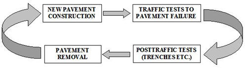
The test track can be divided into independent test items on three subgrade classifications – low strength, medium strength, and high strength. Test items will be trafficked to failure and then reconstructed. In this way, a variety of pavement structures can be tested, including both rigid and flexible designs incorporating unbound aggregate and stabilized bases. A construction cycle includes test pavement construction, instrumentation installation, traffic tests to failure, post traffic testing (trenching activities and other tests), and pavement removal. All pertinent data and information collected at the NAPTF is arranged by construction cycles, each having their own websites.
The rail-based test vehicle has two loading carriages that can be configured for up to 10 wheels per carriage with loads up to 333.75 kN (75,000 lbs) per wheel. The test vehicle is programmed for a controlled aircraft wander simulation. For more information on National Airport Pavement Test Vehicle (NAPTV), visit the NAPTV page.
Sensors have been embedded in the test items to collect data. Sensors are of two types: static and dynamic. Static sensors monitor temperature, moisture, and crack status (resistance) on an hourly basis. Dynamic sensors measure quantities such as strain and pavement deflection in response to the load, and are automatically triggered by NAPTV operations. Sensor data collected during traffic test operations will be processed and stored in computer databases for each construction cycle. All databases are maintained on-site, and are accessible through this website. These databases facilitate retrieval of data for later analysis either by FAA or public researchers.
Since the opening of the NAPTF in 1999, the FAA has completed eight construction cycles. Each construction cycle can be categorized as rigid, or flexible test pavement with the exception of Construction Cycle 1 where both types were tested. The original construction images are shown at the bottom of this webpage. Below is a summary of each construction cycle that has been built and tested at the NAPTF.
|
Construction Cycle
|
Classification (Rigid/Flexible)
|
Purpose
|
|
Construction Cycle 1
|
Both
|
The primary objectives were:
1. Provide full-scale test data to support the new computer-based design procedures that were under development by the FAA
2. Provide full-scale pavement response data for use in airplane landing gear design and configuration studies; and
3. Provide full-scale test data for re-evaluation of the load repetition (alpha) factors used in the CBR method of design for flexible pavements.
|
|
Construction Cycle 2
|
Rigid
|
The main objectives were divided up into 5 different experiments:
CC2 Test Strip - intended to study the effects of slab size and mix design on pavement curling during the early age of the concrete.
CC2 Single Slab - intended to provide experience for the design, placement, and monitoring of the actual PCC test items.
CC2 Twin Slab - intended to compare the behavior of the slab with no fly ash content to the behavior of a companion slab with high fly ash content.
CC2 Test items - were designed and constructed to compare the performance of three types of rigid pavements: concrete slabs on stabilized bases (MRS), concrete slabs on aggregate bases (MRC), and concrete slabs placed directly on subgrade (MRG).
CC2 HMA Overlay - the three rigid airport pavement test items (MRC, MRG, and MRS), built as CC2 main test items at the FAA National Airport Pavement Test Facility (NAPTF) with 12-inch thick concrete slabs on different support systems, were rubblized with a resonant pavement breaker and overlaid with five inches of P-401 hot mix asphalt (HMA). The overlaid pavements were subjected to full-scale accelerated traffic loading to observe the changes in the modulus of the rubblized concrete layer.
|
|
Construction Cycle 3
|
Flexible
|
The primary objective was to provide full-scale test data to improve FAA thickness design procedures for flexible pavements supporting 4-wheel and 6-wheel aircraft gears.
|
|
Construction Cycle 4
|
Rigid
|
The primary objective was to improve the understanding of the influence of design parameters on unbonded concrete overlays of rigid airfield pavements, thus enabling improvement of FAA design methods.
|
|
Construction Cycle 5
|
Flexible
|
The primary objective was to produce data on the relative performance of flexible pavements supporting simple 6-wheel and 4-wheel gears, versus large gear assemblies consisting of multiple 6- and 4-wheel landing gears in close proximity.
|
|
Construction Cycle 6
|
Rigid
|
The primary objective was to determine the effect of concrete flexural strength on rigid pavement structural life.
|
|
Construction Cycle 7
|
Flexible
|
CC7 North
The primary objective of the Perpetual Pavement Test was to extend the Perpetual Pavement concept to airport pavements.
CC7 South
The primary objective of the Overload Test was to determine allowable overload criteria for flexible pavements.
|
| Construction Cycle 8 |
Rigid |
Phase 1 Overload
The primary objective of Phase 1 was to develop rational overload criteria for rigid pavements.
Phase 2 Overlay
The primary object of Phase 2 was to test the performance of a PCC overlay on an existing PCC with Structural Condition Index (SCI) in the 50-80 range.
Phase 3 Joint Comparison
The primary objective of Phase 3 was to compare the performance of Type E (doweled construction) and nonstandard sinusoidal keyed longitudinal joints.
Phase 4 Strength & Fatigue
The primary objective of Phase 4 was to obtain slab strength (rupture strength) for full-scale slabs under a monotonically increasing aircraft gear load, as well as the fatigue strength of rigid pavement slabs under non-wandered traffic.
|
| Construction Cycle 9 |
Flexible |
Fatigue Model and Base Thickness
The primary objective was to verify, refine, or modify the FAARFIELD fatigue model with full-scale test data. In addition, the area was designed to compare the sensitivity of crushed aggregate base course thickness in FAARFIELD.
Geosynthetics
The primary objective of the Geosynthetics test area was to investigate the effects of geosynthetics on airport pavement performance.
Cement-Treated Permeable Base (CTPB)
The primary objective of the CTPB test area was to evaluate the performance of a CTPB course compared to a standard crushed aggregate base course.
Overload
The primary objective of the Overload test area was to follow-up on previous overload tests conducted on Construction Cycle 7 (CC7). Data from CC9 will further the findings from CC7 and support the development of strain criterion for allowable overload in flexible airport pavements.
|
** Click on the construction cycle links in the table above to go the web page pertaining to that construction cycle for more information
General Information on Construction Cycles
All pertinent data and information collected at the NAPTF is arranged by construction cycle. A construction cycle includes test pavement and instrumentation layout, traffic pre and post-test plans, materials testing data, construction test data, traffic data, and post traffic-testing (trenching activities and other tests), and pavement removal. A typical construction cycle at the NAPTF is shown below:
Test Item Designations
Each pavement test item is designated by its construction cycle (CC) number and three characters. The first character denotes the subgrade strength (L-low, M-medium, and H-high). The second character denotes the type of pavement (F-flexible or R-rigid). The third character denotes the type base (S-stabilized, C-conventional, or G-grade). For example, CC1, LRS refers to low-strength subgrade rigid pavement with stabilized base constructed during construction cycle 1. CC3, LFC refers to low-strength subgrade flexible pavement with conventional base constructed during construction cycle 3. LFS refers to low-strength subgrade flexible pavement with a stabilized base. CC4 and CC8 have naming conventions that vary from the others: CC4 uses test section, side (N for north, S for south), and panel number (ie 1N-3) and CC8 uses the test type (O=overlay, JC=joint comparison or SF=strength/fatigue), side (N for north, S for south) and panel number (ie. ON5).
Coordinate System and Sign Conventions
The pavement test items, locations of the sensors, and position of the NAPTV load modules within the NAPTF are oriented in an east/west direction. An x, y, z coordinate system applicable to all construction cycles is used to uniquely identify the location of each of the test items, NAPTV components, and sensor installations. The origin of this system is at the centerline of the pavement surface at the west (low-strength) end of the NAPTF. The longitudinal coordinate x = 0 starts on the pavement centerline on the west end and increases to x = 900 feet on the east end of the NAPTF. Transverse distances are measured relative to the centerline. Positive y coordinates increase to the south to y = 33 feet, and negative coordinates increase to the north to y = -33 feet. Vertical (z) locations are measured from top-of the original pavement surface. The z coordinate is positive downward (instrumentation in an overlay would reflect a negative z coordinate). All coordinates in the NAPTF are measured off of established benchmarks that were set by professional surveying contractors.
Sensors
Each construction cycle at the NAPTF uses a variety of sensors to help capture instrumentation data based on the testing objectives. Sensors are divided into static sensors and dynamic sensors. An example of some of the sensors used are:
|
Static Sensors
|
Dynamic Sensors
|
|
Temperature Gages
|
Multi-Depth Deflectometers (MDD)
|
|
Moisture Gages
|
Asphalt Strain Gages (ASG)
|
|
Resistance Gages
|
Concrete Strain Gages (CSG)
|
|
Humidity Gages
|
Joint Gages
|
|
|
Pressure Cells
|
Static sensor data is commonly collected on an hourly basis using a Campbell Scientific data logger. Dynamic sensor data is collected during traffic testing and monitoring of the construction cycle. The NAPTV triggers the dynamic sensor data loggers during traffic testing. This enables synchronization of the NAPTV load data files with the dynamic sensor data files. Sensor data for each construction cycle can be accessed from databases by clicking on the links in the table above.
Original Construction
The following images show the original construction of the National Airport Pavement Test Facility (NAPTF) and Construction Cycle 1 (CC1). Click on the thumbnail to view a larger image.